Code generation for STM32 (Flashing LED on finite state machines)
This demo discusses the Engee model for controlling the digital output of the STM32 microcontroller.
Introduction
The purpose of this example is to develop the Engee model for the simplest program for controlling the digital output of the STM32F446RE microcontroller using the library's nested states. Engee finite automata.
The example also shows how to add the generated files to the project, followed by programming the controller in the PlatformIO environment for VS Code.
Description of the model
The example model, stm32_blink.engee, consists of two blocks - a block Chart "Blink" and C Function "GPIO_5_OUTPUT (LED)".
The first block implements a control algorithm - state change Out at the output of the block, and the second block initializes the digital control channel GPIO_5 connected to the built-in LED of the NUCLEO-F446RE debugging board, and changes its state during program operation.
State diagram
The state diagram contained in the block Chart, includes the following states:
.png)
Mother: "Period_and_Block" - sets the pulse period FullTime (in the model calculation steps) for the built-in LED to flash and increments the period counter CurrentTime.
Subsidiaries:
- "HIGH" - for the values of the counter
CurrentTime, less than or equal to half of the pulse period, generates a high signal level at the output of the block. - "LOW" - at the values of the counter
CurrentTime, more than half of the pulse period, generates a high signal level at the output of the block.
If the value of the pulse period time counter is equal, the counter is reset in the transition between the "LOW" and "HIGH" states.
Connecting peripherals
The controller's peripheral, GPIO No. 5, used in this example, is fully parameterized in the block C Function models.
First of all, it should be noted that in order for the correct compilation in the development environment of the functions and structures used in this block, it is necessary to include a header file containing prototypes of these functions and structures. stm32f4xx_hal. In the future, this file does not need to be used in the project for the development environment - it is usually already contained in the added libraries.
The figure below shows how to connect the header file in the block C Function.
.png)
In the tab </> StartCode the block contains the configuration and initialization functions of the peripheral - digital input/output No. 5, and in the tab </> OutputCode - the function performed at each step of the model calculation is the function of setting the status of the digital output.
Additional explanations on the code given in the block C Function, are given in the relevant comments.
Simulation results
To simulate the algorithm for generating control pulses, we will load and run the model stm32_blink.engee:
if "stm32_blink" in [m.name for m in engee.get_all_models()]
    m = engee.open( "stm32_blink" );
else
    m = engee.load( "$(@__DIR__)/stm32_blink.engee" );
end

data = engee.run(m);
From the obtained simulation data, we will plot the signal graph Out - status of the built-in LED:
using Plots
plotlyjs()
plot(data["Blink.Out"].time,
     data["Blink.Out"].value,
     label="LED Status", size=(900,300),
     lw=2, legend=:topright)
As can be seen from the graph, a periodic signal with a given pulse frequency and duration is generated at the output of the control algorithm.
Code generation
We will generate the code from the model for subsequent loading of the control algorithm into the microcontroller.:
engee.generate_code( "$(@__DIR__)/stm32_blink.engee",
                     "$(@__DIR__)/stm32_blink_code")
Created in the folder stm32_blink_code header files stm32_blink.h and the original stm32_blink.c we continue to use it when building the project.
Building a project
The development environment through which the project is built and uploaded to the target device is VS Code with the PlatformIO add-on. When working with STM32, this example also uses the STM32 platform and the STM32Cube framework for PlatformIO. The PlatformIO project configuration file platformio.ini It contains the following settings:
[env:nucleo_f446re]
platform = ststm32
board = nucleo_f446re
framework = stm32cube
After creating a new project, you need to add the files generated in Engee and the main program code file to it. main.c (added to the sample folder):
.png)
After that, you can proceed to build the project and download the program.
Running the model on STM32
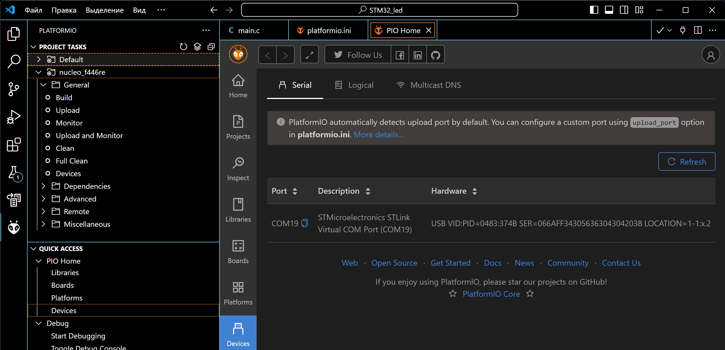
Connect the NUCLEO-F446RE debugging board to the USB port of the computer, after which we can observe the connected device in PlatformIO. The ST-Link V2 driver is required to correctly identify the connection of this card.
.png)
After successful connection, you can proceed to the project build: "PLATFORMIO -> PROJECT TASKS -> nucleo_f446re -> General -> Build". If there are no build errors, we will upload the compiled code to the microcontroller: "PLATFORMIO -> PROJECT TASKS -> nucleo_f446re -> General -> Upload".
As a result of loading the program, an LED with a frequency of 0.5 Hz can be observed on the debugging board.
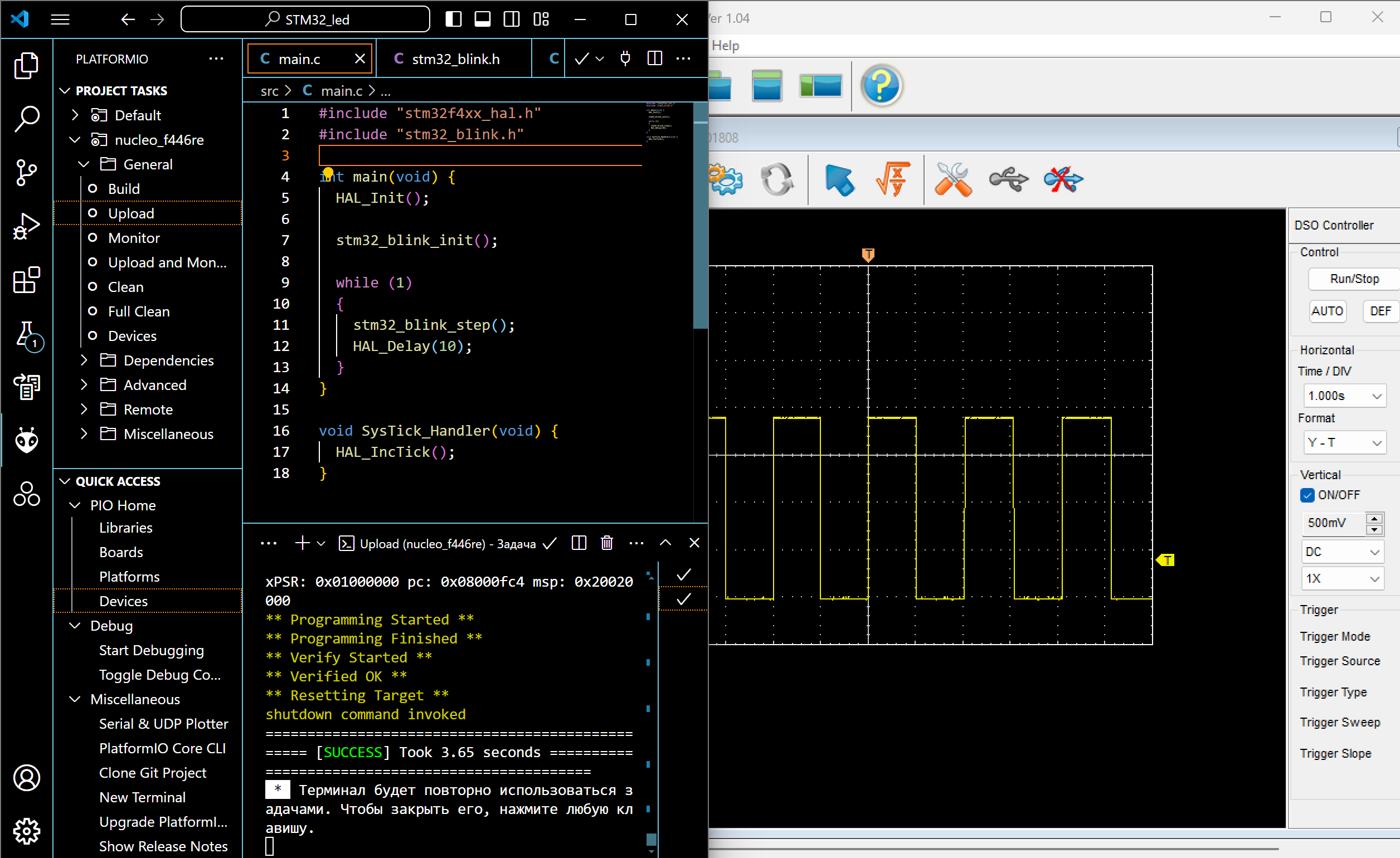
To demonstrate in the example, a Hantec DSO digital oscilloscope was connected to the corresponding pin of the microcontroller, the oscilloscope was output to the serial port of the computer using the DSO Analyzer shell. As can be seen in the figure above, the received signal has a frequency and pulse duration specified in the model.
Conclusion
In this example, we examined the development of the Engee model for the simplest control program, a flashing LED on the STM32F446RE microcontroller as part of the NUCLEO debugging board. The algorithm is implemented using nested block states. Chart from the library Engee finite automata and is suitable for code generation. The process of embedding files generated from the model into the PlatformIO environment project for VS Code with subsequent assembly, download and execution on the target device is considered.