Code generation for STM32 (Button and flashing LED on finite state machines)
This demo discusses the Engee model for controlling the digital input and output of the STM32 microcontroller.
Introduction
The task of this example is to develop a model of Engee a fairly simple program for controlling the digital input and output of the STM32F446RE microcontroller using nested states and library super-transitions. Engee finite automata.
This demo is a functional development of the example Code generation for STM32 (Flashing LED on finite automata).
Description of the model
The example model - stm32_button_blink.engee It includes three blocks C Function configuring and connecting the controller peripherals:
GPIO_PC13_INPUT (USER_BUTTON)- during program initialization, configures and initializes the pin PC13 of the microcontroller as an output. During the step-by-step execution of the program, it returns the status of the digital output.PinState. On the NUCLEO-F446RE debugging board, a user button B1 "USER" is connected to this pin.GPIO_5_OUTPUT (LED)- during program initialization, configures and initializes the pin PA5 of the microcontroller as an input. In the course of step-by-step execution, assigns it a state fromPinState. On the NUCLEO-F446RE debugging board, an LED LD2 "GREEN" is connected to this pin.DELAY- during program initialization, configures and initializes the internal timerSysTick. During the step-by-step execution, it generates a delay with its help.Ts, equal to the modeling step.
Configurable parameter Ts defined by the function PreLoadFunc in callbacks and is used as the step size in the model solver, the input value for the block DELAY and the block calculation step Pulse Generator.
Block Pulse Generator simulates the periodic pressing of the B1 button on the debugging board during the simulation. The duration of the press is 10 seconds, the frequency is 20 seconds. During the simulation, the signal of this block passes through the digital input block unchanged.
In the block Blink using the state diagram the logic of pulse generation for flashing the LED is implemented.
State diagram
In development of the state diagram from the example Code generation for STM32 (Flashing LED on finite automata), containing one parent state, the block Chart This example contains two parent states with super transitions between them.
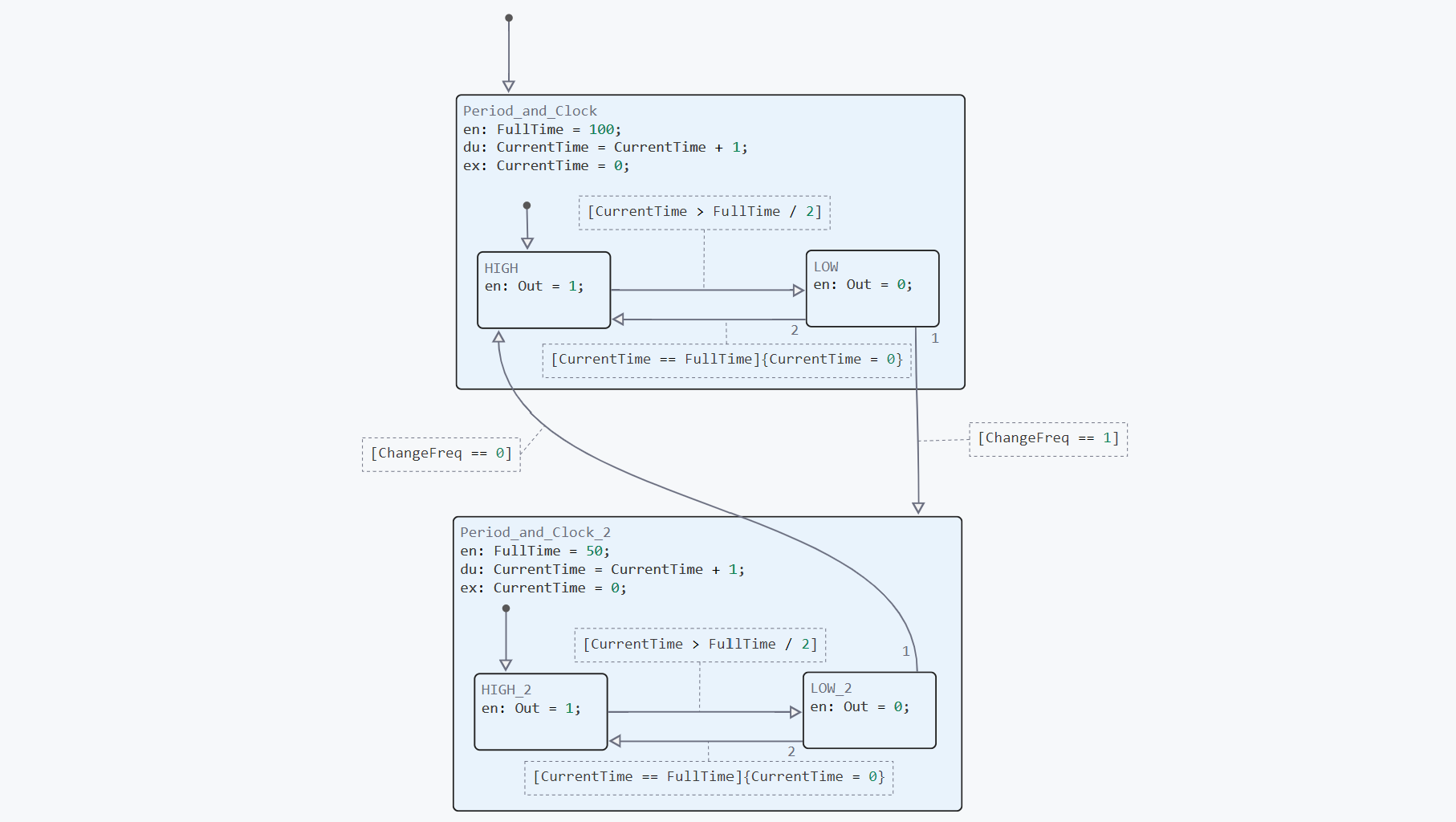
Internal variable FullTime sets the duration of the LED blinking periods - seconds in the parent state Period_and_Clock if the B1 button is not pressed and the input variable ChangeFreq equal to , and seconds in the parent state Period_and_Clock_2 in the opposite case. When in the parent states, an increment occurs, and when exiting them, the counter variable is reset. CurrentTime.
Connecting peripherals
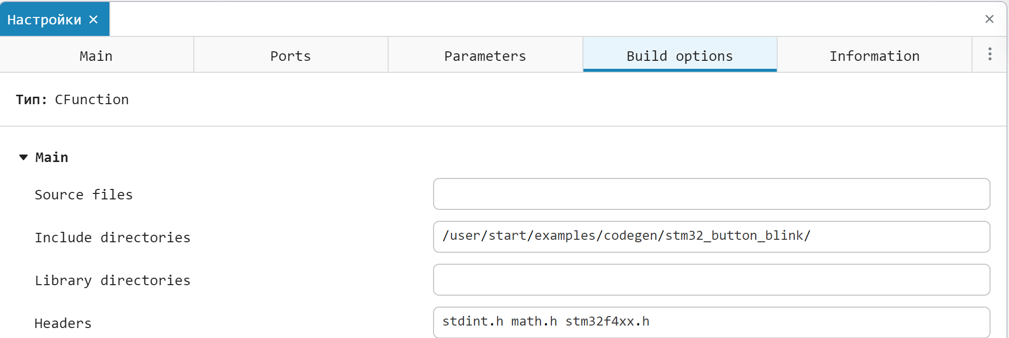
Unlike the example Code generation for STM32 (Flashing LED on finite state machines), which uses the STM32 hardware Abstraction Layer (HAL) library to work with peripherals, where peripheral blocks use register accesses according to the header file stm32f4xx.h. In the Build options of the blocks C Functions this file is being connected. The file itself stm32f4xx.h located in the example folder, it is used only for modeling and code generation, there is no need to add it to the IDE project later.
.png)
Additional explanations to the code of the peripheral blocks are given in the comments to the code.
Simulation results
To simulate the algorithm for generating control pulses, we will load and run the model at the touch of a button. stm32_button_blink.engee:
if "stm32_button_blink" in [m.name for m in engee.get_all_models()]
    m = engee.open( "stm32_button_blink" );
else
    m = engee.load( "$(@__DIR__)/stm32_button_blink.engee" );
end

data = engee.run(m);
From the obtained simulation data, we will plot the signal graphs Blink.Out - the status of the built-in LED and Pulse Generator.1 - button status:
using Plots
plotlyjs()
plot(data["Pulse Generator.1"].time,
     data["Pulse Generator.1"].value,
     label="Frequency switching", size=(900,300),
     lw=2, legend=:topright)
plot!(data["Blink.Out"].time,
     data["Blink.Out"].value,
     label="LED Status", lw=2, )
As can be seen from the graphs, periodic signals for the LED are generated in the model with a frequency that can be changed at the touch of a button.
Code generation
We will generate the code from the model for subsequent loading of the control algorithm into the microcontroller.:
engee.generate_code( "$(@__DIR__)/stm32_button_blink.engee",
                     "$(@__DIR__)/stm32_button_blink_code")
Created in the folder stm32_button_blink_code header files stm32_button_blink.h and the original stm32_button_blink.c we continue to use it when building the project.
Project preparation in the development environment
The development environment through which the project is built and uploaded to the target device is VS Code with the PlatformIO add-on. The environment and connection configurations correspond to those already described in the example Code generation for STM32 (Flashing LED on finite automata).
After creating a new project, you need to add the files generated in Engee and the main program code file to it. main.c (added to the sample folder):
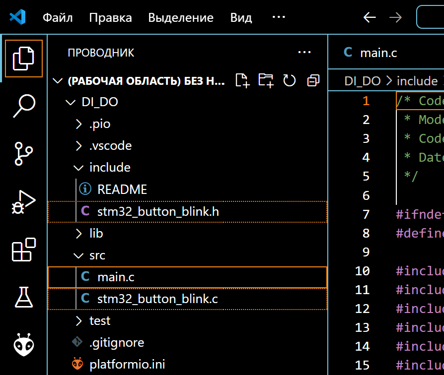
After that, you can proceed to build the project and download the program.
Running the model on STM32
Connect the NUCLEO-F446RE debugging board to the USB port of the computer, after which we can observe the connected device in PlatformIO. The ST-Link V2 driver is required to correctly identify the connection of this card.
After successful connection, proceed to build the project: "PLATFORMIO -> PROJECT TASKS -> nucleo_f446re -> General -> Build". If there are no build errors, we will upload the compiled code to the microcontroller: "PLATFORMIO -> PROJECT TASKS -> nucleo_f446re -> General -> Upload".
As a result of loading the program, an LED with a frequency of 1 Hz can be observed on the debugging board. When pressing the B1 button, the LED flashes at 2 Hz.
To demonstrate in the example, a Hantec DSO digital oscilloscope was connected to the corresponding pin of the debugging board (D13), and the waveform was read through the serial port of the computer using the DSO Analyzer shell. As you can see in the animation above, the frequency of the output signal doubles when the built-in button is pressed.
Conclusion
In this example, we examined the development of the Engee model for a program for controlling a flashing LED by a signal from a digital input on a STM32F446RE microcontroller as part of the NUCLEO debugging board. The algorithm is implemented using nested states and super block transitions. Chart from the library Engee finite automata and is suitable for code generation. The developed model is embedded with the generated files in the PlatformIO environment project for VS Code, followed by assembly, download, and execution on the target device.