Generating Verilog code from a model
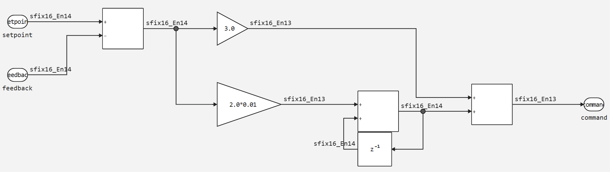
This example uses the model from the following demo <https://engee.com/helpcenter/stable/en/interactive-scripts/base_simulation/PID_fixed.html >, and given the use of fixed-point data types in it, we can afford to generate code from them in Verilog languages. We will generate the code from the PID controller block.
Now we will generate code in the Verilog language from this model. To do this, we will set the attribute in the program control function of the code generator target="verilog".
Verilog is a hardware description language (HDL) used for designing and modeling digital systems such as FPGA and ASIC circuits. It allows you to describe the structure and behavior of digital circuits at the level of registers and logic, which makes it a basic tool for hardware engineers. Verilog supports simulation of parallel processes, which is critical for circuits with a large number of simultaneous components.
The main applications of Verilog are listed below.
-
FPGA and ASIC design: Verilog allows you to describe complex digital systems that can then be synthesized into physical circuits on FPGAs or integrated circuits.
-
Simulation and Verification: Verilog provides simulation capabilities, allowing you to test and debug circuits before implementing them on hardware.
-
Development automation: synthesizers translate Verilog code into optimized logic circuits, which simplifies the process of creating and testing hardware components.
Verilog is used in projects that require high-speed data processing and reliable parallel execution.
engee.generate_code("$(@__DIR__)/pid_fixed.engee", "$(@__DIR__)/verilog"; subsystem_name="SubSystem", target="verilog")
Now let's analyze the results.
.png)
As we can see, the code has been successfully generated and can be applied in further development, the code itself is presented below.
module pid_fixed_SubSystem(
  input         clock,
                reset,
  input  [15:0] io_setpoint,
                io_feedback,
  output [15:0] io_command
);

  reg  [15:0] UnitDelay_state;
  wire [15:0] _AddAccum_T = io_setpoint - io_feedback;
  wire [28:0] _Gain_2_new_T_1 = {{13{_AddAccum_T[15]}}, _AddAccum_T} * 29'hA4;
  wire [29:0] _Gain_new_T_1 = {{14{_AddAccum_T[15]}}, _AddAccum_T} * 30'h6000;
  wire [15:0] _Add_1Accum_T = {_Gain_2_new_T_1[28:14], 1'h0} + UnitDelay_state;
  always @(posedge clock) begin
    if (reset)
      UnitDelay_state <= 16'h0;
    else
      UnitDelay_state <= _Add_1Accum_T;
  end // always @(posedge)
  assign io_command = _Gain_new_T_1[29:14] + {_Add_1Accum_T[15], _Add_1Accum_T[15:1]};
endmodule
Conclusion
In this example, we looked at the possibilities of code generation in Engee and showed you how to use this tool for your projects.