Code generation for MIC32 (Sawtooth Signal Generator)
This demo shows the development of the Engee model for a two-channel sawtooth signal generator, followed by code generation and execution on a MIK32 NUKE V0.3 debugging board.
Introduction
The target device used in this demo is the MIK32 NUKE V0 debugging board.3 based on microcontroller [K1948VK018 MIK32 Amur](https://mikron.ru/products/mikrokontrollery/mk32-amur /). In the Engee model developed in this example, sawtooth signals are generated and transmitted to digital-to-analog converters (DACs) of the microcontroller, while the modulated signal of the second DAC is formed with a fixed phase shift. In addition, the peripheral of the controller is also connected in the model. The code was compiled and uploaded to the microcontroller from VS Code with the PlatformIO extension.
Description of the model
The model of this example - mik32_dac.engee. The following blocks are used to connect and work with the microcontroller's peripherals: C Function. The counter block Counter Free-Running generates a sawtooth signal in accordance with the specified bit depth of the resulting number, when the maximum value is reached, the counter is reset to zero and continues operation.
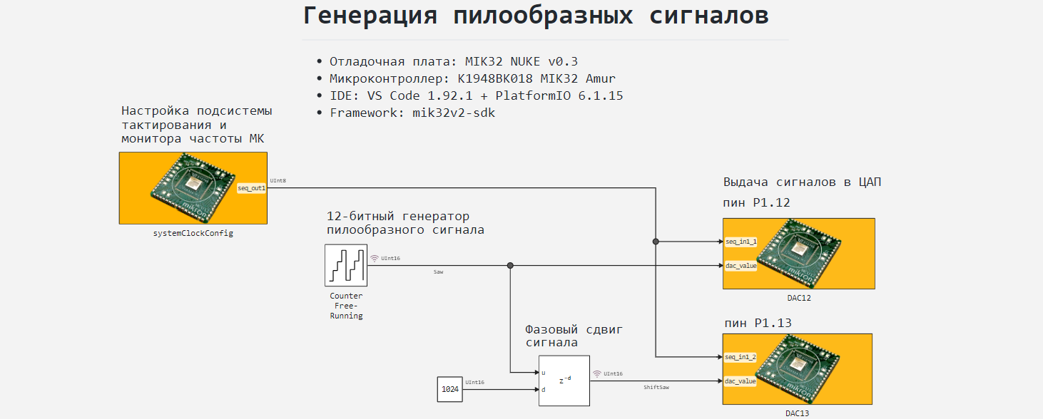
The phase shift of the signal for the second DAC is organized by the block Variable Integer Delay - it sets the maximum buffer size for the stored previous values of the signal, and the incoming value for the input d A fixed phase shift of the signal is determined from the constant block.
Connecting peripherals
To work with the MIC32 peripherals, the model uses the following blocks C Function: systemClockConfig, DAC12 and DAC13. The blocks have the following purpose:
systemClockConfig- adjusts the clock subsystem and the frequency monitor of the microcontroller;DAC12- initializes DAC 1 and generates an output value at output P1.12;DAC13- initializes DAC 2 and generates an output value at output P1.13.
The DACs of the microcontroller are based on two-stage 6-bit resistive arrays, the internal reference voltage of the DAC is 1.2 V. The total bit depth is 12 bits.
Each of the blocks C Function connects the header file for the corresponding peripheral from the MIK32 HAL library. Blocks DAC12 and DAC13 among other things, they connect header files mik32_dac12_typedef.h and mik32_dac13_typedef.h to declare the structure name of the DAC variables. The header files to be connected are contained in the directory include/ an example. The following is an example of connecting header files in a block DAC12.
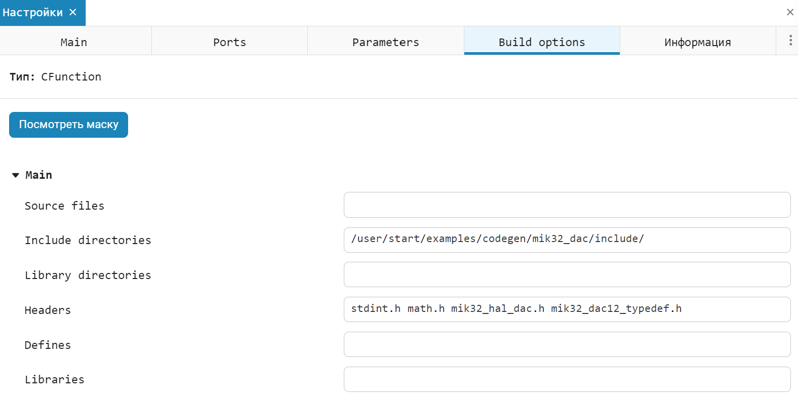
A more detailed description of how the code works in blocks C Function given in the comments to the code.
Simulation results
To simulate a sawtooth signal generator download and run the model mik32_dac:
# @markdown **Software modeling management:**
# @markdown Requires you to enter only the model name
имя_модели = "mik32_dac" # @param {type:"string"}
if the model name is in [m.name for m in engee.get_all_models()]
    model = engee.open( model name );
else
    модель = engee.load( "$(@__DIR__)/"*имя_модели*".engee" );
end
data = engee.run(model);
For convenience and clarity of application, in the example of service code cells, [code masking] is used. ячеек](https://engee.com/helpcenter/stable/en/interactive-scripts/language_basics/code_cell_masks.html). The next cell of the code is updated automatically.
# @markdown **Plotting graphs:**
# @markdown Plots.jl library, gr backend()
Формат = :svg # @param [":svg", ":png"] {type:"raw"}
gr(format = Format)
Ширина = 900 # @param {type:"integer"}
Высота = 300 # @param {type:"integer"}
Сигнал_1 = "Saw" # @param {type:"string"}
Подпись_1 = "DAC 1" # @param {type:"string"}
Сигнал_2 = "ShiftSaw" # @param {type:"string"}
Подпись_2 = "DAC 2" # @param {type: "string"}
Расположение_подписей = :topleft # @param [":none", ":topleft", ":top", ":topright", ":left", ":right", ":bottomleft",":bottom",":bottomright", ":outerright", ":outerleft", ":outertop", ":outerbottom", ":outertopright", ":outertopleft", ":outerbottomright", :outerbottomleft] {type:"raw"}
Заголовок = "DAC signals" # @param {type:"string"}
Подпись_X = "Simulation time, with" # @param {type:"string"}
Подпись_Y = "Signal amplitude" # @param {type:"string"}
plot(size = (Width, Height), legend = Location of Labels, title=Title, xlabel=Caption_X, ylabel=SIGN_U)
plot!(data[Signal_1].time, data[Signal_1].value;
      label = Caption_1, lw = 2)
plot!(data[Signal_2].time, data [Signal_2].value;
      label = Caption_2, st = :step, lw = 2)
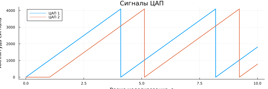
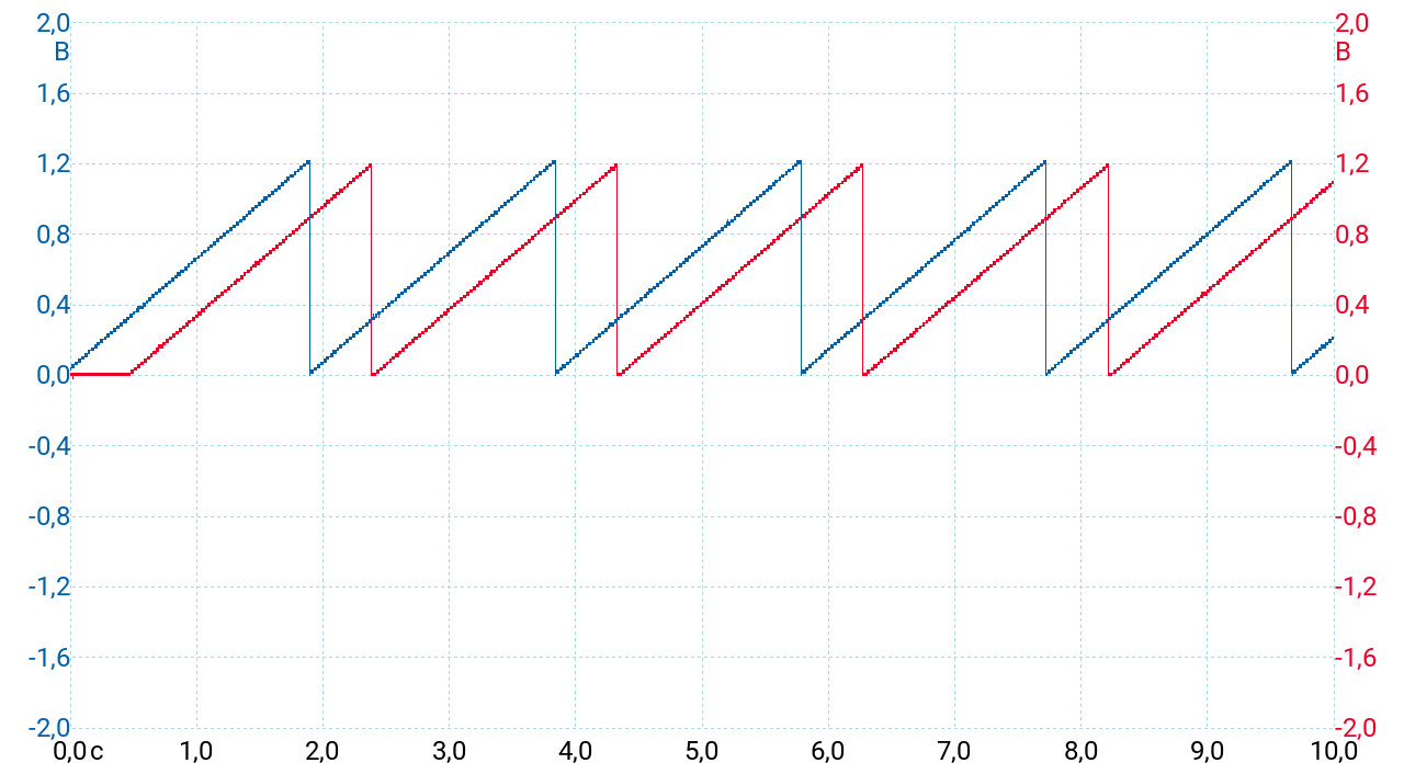
As can be seen from the graphs obtained, sawtooth signals are modeled with a given amplitude. , the signal for the second DAC is transmitted with a delay of 1024 samples.
Code generation
Generate код from the model for subsequent loading of the algorithm developed in the model into the microcontroller:
# @markdown **Code generation:**
# @markdown A folder for the code generation results will be created in the script folder:
папка = "code" # @param {type:"string"}

# @markdown Code generation for the subsystem:
включить = false # @param {type:"boolean"}
if(enable)
    подсистема = "" # @param {type:"string"}
    engee.generate_code( "$(@__DIR__)/"*имя_модели*".engee", "$(@__DIR__)/"*папка;
                     subsystem_name = subsystem)
else
    engee.generate_code( "$(@__DIR__)/"*имя_модели*".engee", "$(@__DIR__)/"*папка)
end
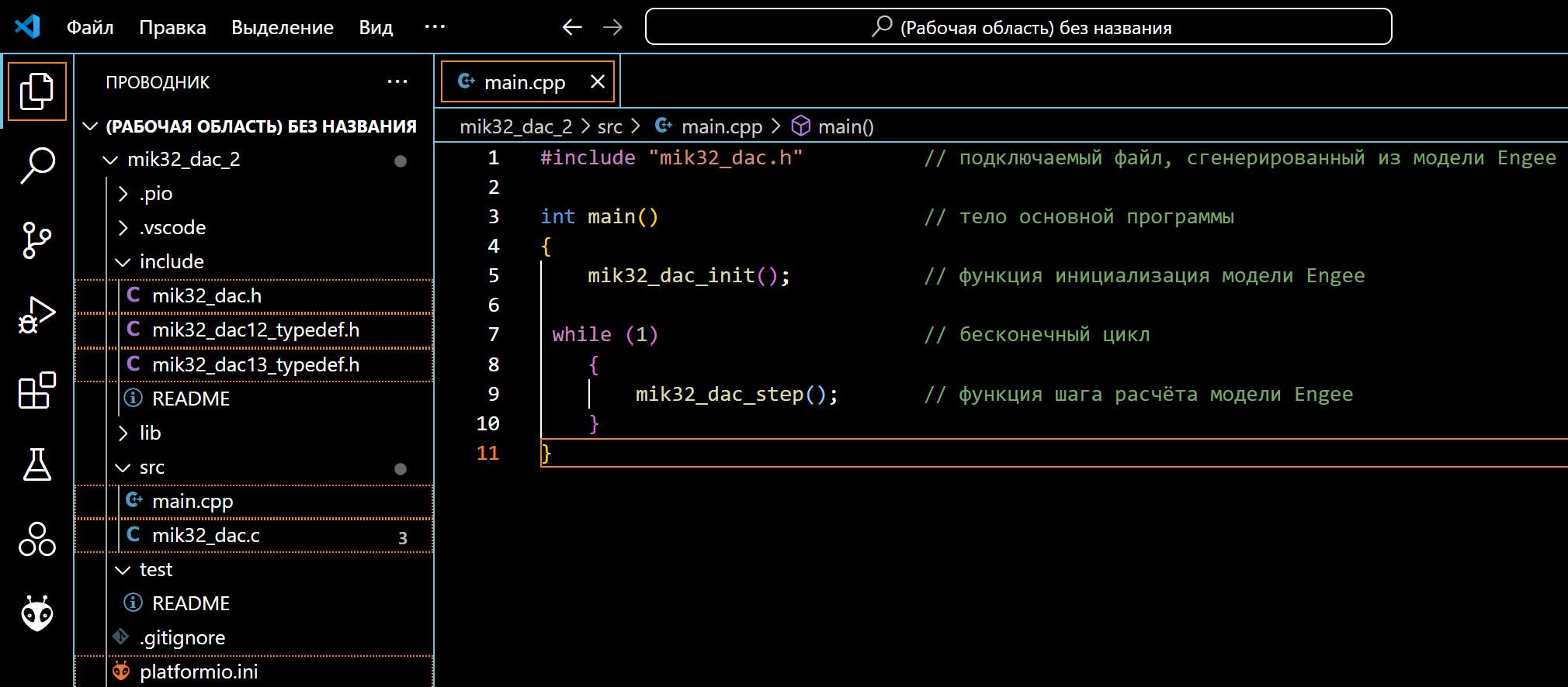
The files received in the specified folder are header files. mik32_dac.h and the original mik32_dac.c we continue to use it when building the project. Generated main program file main.c It will not be used in the project. It has been prepared for code execution in the development environment. main.cpp located in the root folder mik32_dac an example.
Project preparation in the development environment
The development environment through which the project is built and uploaded to the target device is VS Code with the PlatformIO add-on. The environment and connection configurations are not considered in this example, as they are described in detail on ресурсах the developer of the controller.
From the sample directory, we will transfer the generated files to the PlatformIO project., main.cpp, mik32_dac12_typedef.h mik32_dac13_typedef.h and the configuration file platformio.ini.
After that, you can proceed to build the project and download the program.
Code execution on MIC32
Connect the debugging board MIK32 NUKE V0.3 to the USB port of the computer, after which we can observe the connected device in PlatformIO. A USB driver is required to correctly identify the connection of this card. The example uses the driver libusbK.
After successful activation, we will proceed to building the project.:
“PLATFORMIO -> PROJECT TASKS -> mik32v2 -> General -> Build”.
If there are no build errors, we will upload the compiled code to the microcontroller.:
“PLATFORMIO -> PROJECT TASKS -> mik32v2 -> General -> Upload”.
To remove the generated pins P1.12 and P1.13 In this example, a digital PC oscilloscope PcoScope 2205A is used for debugging DAC signals, the measurement results are output to the PicoScope 7 T&M; software.
As can be seen from the waveforms, the sawtooth signal graphs have a maximum voltage amplitude (1.2 V), which corresponds to the set output signal level (4095). The signal of the second DAC has a preset phase shift.
Conclusion
In this example, we reviewed the development of the Engee model for a program for generating sawtooth signals with a resolution of 12 bits and a fixed phase shift for the K1948VK018 MIK32 Amur microcontroller as part of the MIK32 NUKE V0.3 debugging board. The developed model is embedded with the generated files in the PlatformIO environment project for VS Code, followed by assembly, download, and execution on the target device.