Code generation for Arduino (linear frequency modulation with low-pass filter)
This demo example calculates, simulates, and executes a digital low-pass filter with linear frequency modulation on the target device.
Introduction
The purpose of this example is to develop a low-pass filter based on the specified parameters. To calculate it, we will use the Julia DSP library. We will check the operation of the filter in the Engee model on the signal received by linear frequency modulation. After generating the code from the Engee model, we will reproduce the signal filtering on the Arduino debugging board.
Hardware part
This example uses an Arduino MEGA 2560 debugging board. The output signal is generated at output No. 9. Digital-to-analog signal conversion is performed using PWM and an RC low-pass filter. The PWM frequency is 62.5 kHz, the cutoff frequency of the RC filter is 14.185 kHz, and the filter order is 2. The connection diagram is shown in the figure below.
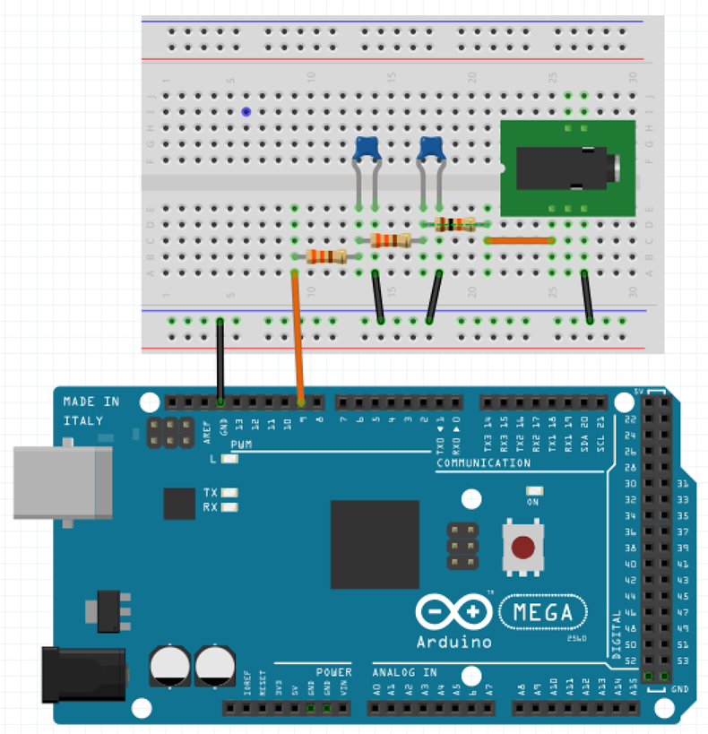
Parameters of the RC circuit: . At the output of the circuit through a current limiting resistor A 3.5mm audio output jack is connected to output the signal to the speaker.
Description of the model
The functional part of the model considered in this example is a subsystem FM forming a well variable Duty. This variable in the user sketch will be passed to the PWM controller module to generate an analog output signal.
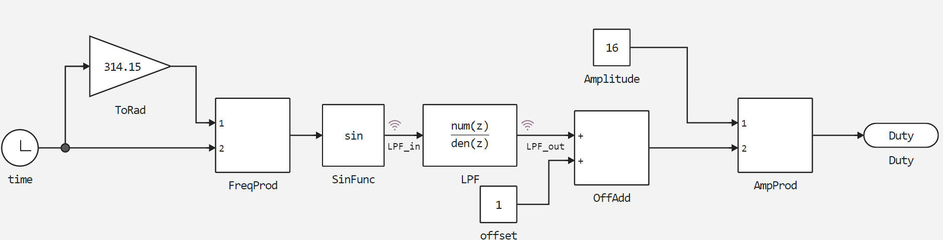
Subsystem contents FM describes linear frequency modulation using the formula . The frequency of the signal varies linearly: After passing through the low-pass filter in the block LPF filtered signal gets offset and scaled. This is necessary for the correct and most accurate formation of the PWM borehole. The PWM resolution in this example is only 5 bits, but this allows you to achieve a high PWM frequency.
.png)
The PWM borehole is determined by the formula .
It should be noted that in order to further save the computing power of the target device, the change in signal frequency is directly related to the simulation time. Thus, the frequency of the modulated signal at a certain moment will exceed both the Nyquist frequency and the sampling frequency. Therefore, for the correct presentation of the filter results, it is necessary to select a cutoff frequency that is lower than the Nyquist frequency.
Calculation of the low-pass filter
For low-pass filtering, choose an elliptical filter with the parameters:
- the sampling frequency is 2000 Hz (hence the Nyquist frequency is 1000 Hz),
- cutoff frequency - 400 Hz,
- number of poles - 6,
- the unevenness of the characteristic in the bandwidth is 1 dB,
- attenuation in the delay band is 60 dB.
# Connecting libraries
neededLibs = ["WAV", "DSP"]
for lib in neededLibs
    try
        eval(Meta.parse("using $lib"))
    catch ex
        Pkg.add(lib)
        eval(Meta.parse("using $lib"))
    end
end
fs = 2000
fp = 400;
n = 6;
Rp = 1;
Rs = 60;
Calculate the coefficients of the polynomials of the numerator and denominator of the filter transfer function:
methods(Lowpass)
using DSP;
myfilt = digitalfilter(Lowpass(fp; fs), Elliptic(n, Rp, Rs));
b = coefb(myfilt);
a = coefa(myfilt);
Copy the obtained coefficients into the numerator and denominator of the block LPF models.
Simulation results
Download and execute the created model:
if "chirp_lpf" in [m.name for m in engee.get_all_models()]
    m = engee.open( "chirp_lpf" );
else
    m = engee.load( "$(@__DIR__)/chirp_lpf.engee" );
end

data = engee.run(m);
From the obtained model data, we will plot the output variables - the signal at the input and output of the low-frequency: LPF_in and LPF_out accordingly.
using Plots
plotlyjs()
plot(data["LPF_in"].time, data["LPF_in"].value,
    label="Before the low-frequency", size=(900,300), lw=2, st=:step)
plot!(data["LPF_out"].time, data["LPF_out"].value,
    label="After the low-frequency", size=(900,300), lw=2, st=:step)
xlabel!("Time, seconds")
ylabel!("Meaning")
As can be seen from the graph, the filter performs signal conversion according to the specified parameters.
Uploading code to Arduino
To upload to Arduino, you need to generate code from the subsystem FM:
engee.generate_code( "$(@__DIR__)/chirp_lpf.engee",
                     "$(@__DIR__)/chirp_lpf_code";
                     subsystem_name="FM")
We will connect the files generated in the specified directory in the user sketch. chirp_lpf.ino. Download these files and upload them to Arduino MEGA using Arduino IDE.
Code execution on Arduino
After successful compilation and uploading of the sketch to the target device, we will connect a digital oscilloscope at the output of the RC filter and remove the variable component of the generated signal.
For the demonstration, a digital oscilloscope Hantec DSO was used with connection to a computer and data output to the DSO Analyzer program.
As you can see, when the frequency of a sinusoidal signal increases after 400 Hz, its amplitude is suppressed. To better represent the operation of the model with a digital filter, a speaker was connected to the output of the RC circuit, and the resulting sound was recorded in a file. chirp_lpf_audio.wav. The next code cell allows you to upload the received audio file to the script and play it back. Play the audio track to make sure that the developed model and filter are working properly.
using WAV, Base64
x, fs = wavread( "$(@__DIR__)/chirp_lpf_audio.wav" );

buf = IOBuffer();
wavwrite(x, buf; Fs=fs);
data = base64encode(unsafe_string(pointer(buf.data), buf.size));
markup = """<audio controls="controls" {autoplay}>
              <source src="data:audio/wav;base64,$data" type="audio/wav" />
              Your browser does not support the audio element.
              </audio>"""
display( "text/html", markup );
Conclusion
In this example, we looked at the operation of a digital elliptical low-pass filter that processes the LFM signal. The calculated filter corresponds to the specified parameters both during modeling and when it is performed on the target device.