Verilog-implementation of 4-FSK character encoding (without FM)
Here we will look at working with 4-FSK (Frequency Shift Keying) in Engee.
Frequency modulation is a type of modulation in which information is encoded by changing the frequency of a signal. 4-FSK, four-level frequency manipulation, is a type of modulation used in DMR (Digital Mobile Radio), and it is optimal for use in PMR (Professional Mobile Radio) systems.
We will also generate the Verilog code from this model and test its performance in Vivado.
Verilog is a hardware description language used to develop electronic systems.
Verilog is needed in the design, verification, and implementation of analog, digital, and mixed electronic systems at various levels of abstraction.
Let's declare auxiliary functions
function run_model( name_model)
    Path = (@__DIR__) * "/" * name_model * ".engee"

    if name_model in [m.name for m in engee.get_all_models()] # Checking the condition for loading a model into the kernel
        model = engee.open( name_model ) # Open the model
        model_output = engee.run( model, verbose=true ); # Launch the model
    else
        model = engee.load( Path, force=true ) # Upload a model
        model_output = engee.run( model, verbose=true ); # Launch the model
        engee.close( name_model, force=true ); # Close the model
    end
    sleep(0.01)
    return model_output
end
Model analysis
We will study two variants of the model. One uses the standard selection logic implemented by switching. The second version of the block is implemented using a mathematical formula. Using such methods, it is often necessary to change algorithms beyond recognition when developing systems in order to optimize their performance in terms of speed or resources.
The table below is based on which the model was developed.
symbol = [-3, -1, 1, 3]
bits = [[0, 0], [0, 1], [1, 0], [1, 1]]

println(join(["bits: $bit, symbol: $f" for (f, bit) in zip(symbol, bits)], "\n"))
The screenshots below show the developed model.
The source block is 4-FSK.
.png)
As we can see, there is significantly less logic in the block implemented using the formula than in the original block. In addition, all multiplication blocks in it use multiplication by 2, and, accordingly, when generating code, this logic will be a one-bit shift.
.png)
We can also note that shorter data types are used in this case than in the case of the original block, where Int8 was used.
Let's briefly touch on the topic of fixed-point data types. This data type is set by the command fi(X, 1, 16, 5), where from left to right the parameters are:
- Number values;
- sign (1-signed, 0-unsigned);
- Full word size;
- The size of the fractional part.
Next, let's look at a simple example.
x = fi(7.5, 1, 7, 5)
y = fi(7.5, 1, 7, 3)
println("x: $x")
println("y: $y")
As we can see, in the first case, the number 7.5 went into overflow.
x+y
You can also see that when these two numbers are added together, more memory is allocated for them than was originally allocated.
Checking the model's operability
Now let's analyze the correspondence of the two implementations with each other. First, let's run the model.
bit_1 = 1; bit_2 = 1;
println("Inp_bit: $([bit_1, bit_2])")

println()
@time run_model("FSK_V") # Launching the model.
Now let's compare the results. As we can see, both results correspond to the original table.
Symbol_math = collect(Symbol_sim).value[end]
println("Symbol_math: $Symbol_math")
Symbol_switch = collect(Symbol_sim_switch).value[end]
println("Symbol_switch: $Symbol_switch")
To verify the final project, we can present the block from which we will continue to generate the code in the form of a formula. Let's make sure that the formula is identical to the model.
Symbol_ref = 2 * (2 * bit_1 + bit_2) - 3
println("Symbol_ref: $Symbol_ref")
println("Symbol_sim: $Symbol_math")
Let's generate the code from the 4-FSK modulator block
Let's start with the code generation command. Below is information about the possibilities of using the generator.
? engee.generate_code
Now let's set the target platform in the model.
.png)
Let's run the code generation. Due to the fact that the target platform is explicitly set in the model settings, we will not need the target selection line.
engee.generate_code(
"$(@__DIR__)/FSK_V.engee",
"$(@__DIR__)/V_Code",
subsystem_name="4-FSK modulator math",
# target="verilog"
)
Working with Vivado
Now let's test the received code in Vivado and download the received files.
.png)
Create an empty project.
.png)
Add the generated file.
.png)
Let's define the target platform for our project.
.png)
Now we can look at the final schematics of our project. It turned out to be very simple.
.png)
Let's synthesize and implement the project. As we can see, timings are not defined. This is due to the fact that the input ports of our block are empty, nothing is being supplied to them.
.png)
We can verify this by looking at the simulation results as well. All inputs and outputs are undefined.
.png)
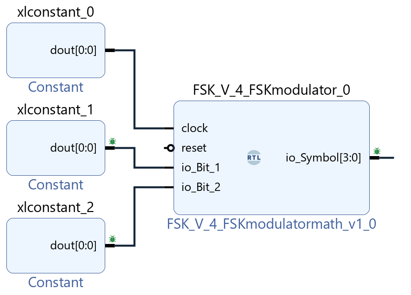
Let's fix this and add a binding to our block by setting the input ports as constants.
.png)
.png)
Now let's repeat the simulation.
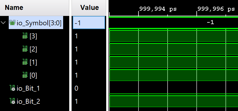
The result of the simulation may seem incorrect, but let's analyze the generated logic point by point, provided that a pair of bits [0,1] is received at the input. Let's start by analyzing the results using the formula we have developed.
Symbol_ref = 2*(2*0+1)-3 # [0,1]
println("Expected result: $Symbol_ref")
Now let's move on to our code.:
(io_Symbol = {{1'h0, io_Bit_1, 1'h0} + {2'h0, io_Bit_2}, 1'h0} - 4'h3)
- {1'h0, 0, 1'h0}: 000
- {2'h0, 1}: 001
- {0,0,0} + {0,0,1}: 001
- {001, 0}: 0010
- 4'h3: 0011
Now let's move on to the answer. If we take bit subtraction, the result is: [1111].
- 0010 - 0011 = -1
- We take the module: 1: 0001
- Invert the bits: 0001: 1110
- Add 1: 1110 + 1: 1111
Based on the theses described above, it can be argued that our simplified implementation of the 4-FSK modulator works correctly.
Conclusion
In this example, we analyzed the possibilities of generating and verifying Verilog code in Engee, and made sure that this approach to developing FPGA systems is applicable and relevant. Moreover, it can significantly speed up the development process due to the ability to instantly edit and test the model.