Code generation for Arduino (Direct Digital Synthesis)
This example shows a model of direct digital synthesis (DDS) of signals with subsequent execution on Arduino.
Introduction
The task of direct digital synthesis is to generate signals of a given shape at the output of a generator with adjustable parameters. In this example, switching over an external discrete signal between five output waveforms will be implemented - sawtooth with a positive and negative slope, triangular, sinusoidal and meander. The frequency and amplitude of the output signal will be adjusted using two external analog signals.
Hardware part
In this example, the Arduino MEGA 2560 debugging board is used as the target device. The output signal is generated at output No. 9. Digital-to-analog signal conversion is performed using PWM and an RC low-pass filter. The PWM frequency is , the cutoff frequency of the RC filter , the filter order is 2. Parameters of the RC circuit: .
The signal for switching the output waveform is sent to digital input No. 2 from a push-button contact with a circuit for eliminating rattling on a pull-up resistor and the shunt capacitor .
To control the frequency and amplitude of the output signal, resistance potentiometers are connected to the analog inputs A0 and A1 of the Arduino debugging board .
The connection diagram of the elements is shown in the figure below.
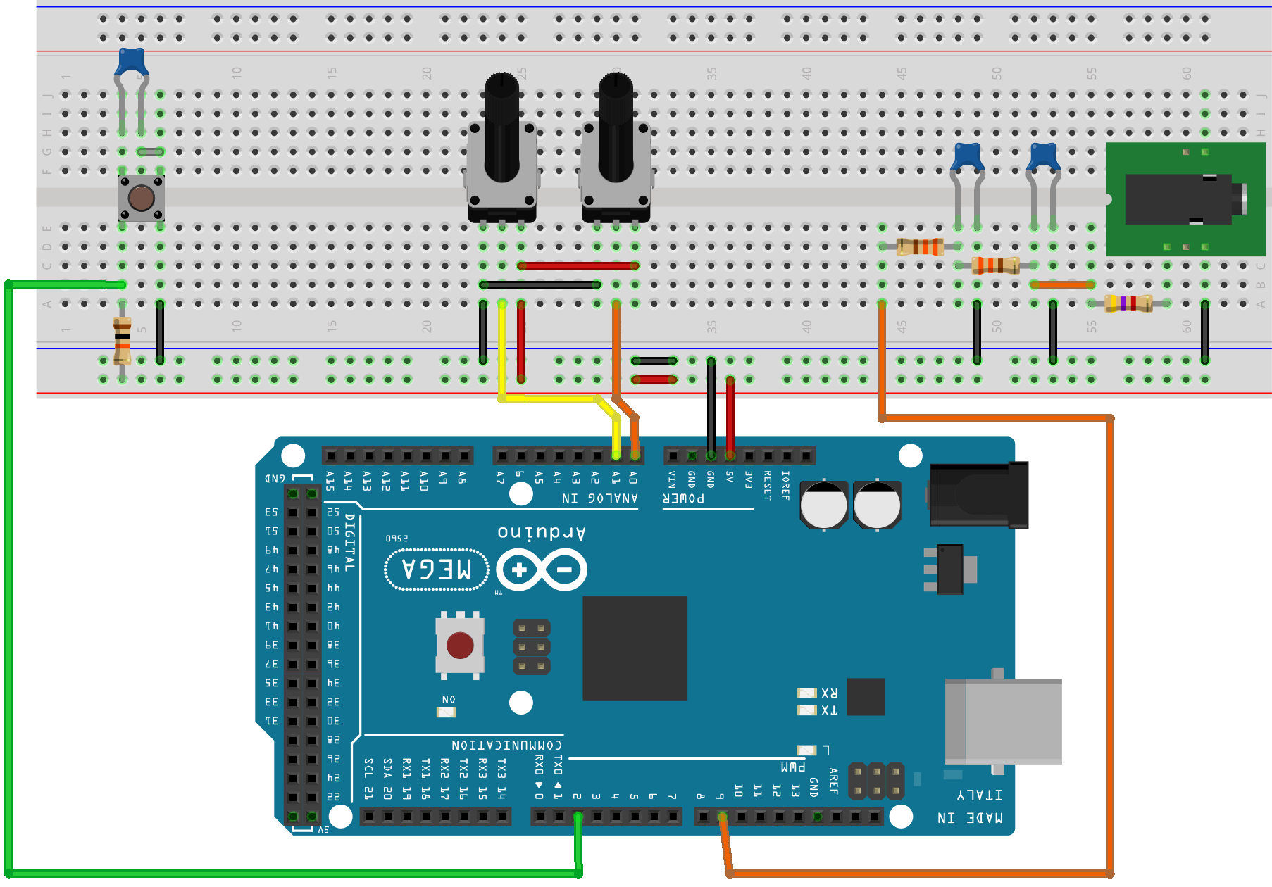
The output signal is captured by a Hantec DSO oscilloscope at the output of the low-pass filter. It is also used to output a signal to the speaker after the filter through a current limiting resistor. A 3.5mm audio output jack is connected.
Description of the model
To interact with the controller peripherals in the model arduino_dds Four blocks are used C Function:
DigitalInput_Mode- initializes digital input No. 2, polls the input status. When modeling in Engee, it generates a periodic sawtooth signal to organize a negative edge at the input of the counter unit.ModeCounterand switching the output waveform.AnalogInput_Freq- polls the frequency value on the analog input A0. When modeling in Engee sets the conditional frequency of the output signal .AnalogInput_Amp- polls the amplitude value on the analog input A1. When modeling in Engee sets the conditional amplitude of the output signal .HFPWM_Output- initializes PWM operation at output No. 9 with the maximum available frequency (62.5 kHz) and transmits a new duty cycle value to the PWM controller module.
Details about the operation of the peripheral blocks are given in the comments to the code in these blocks.
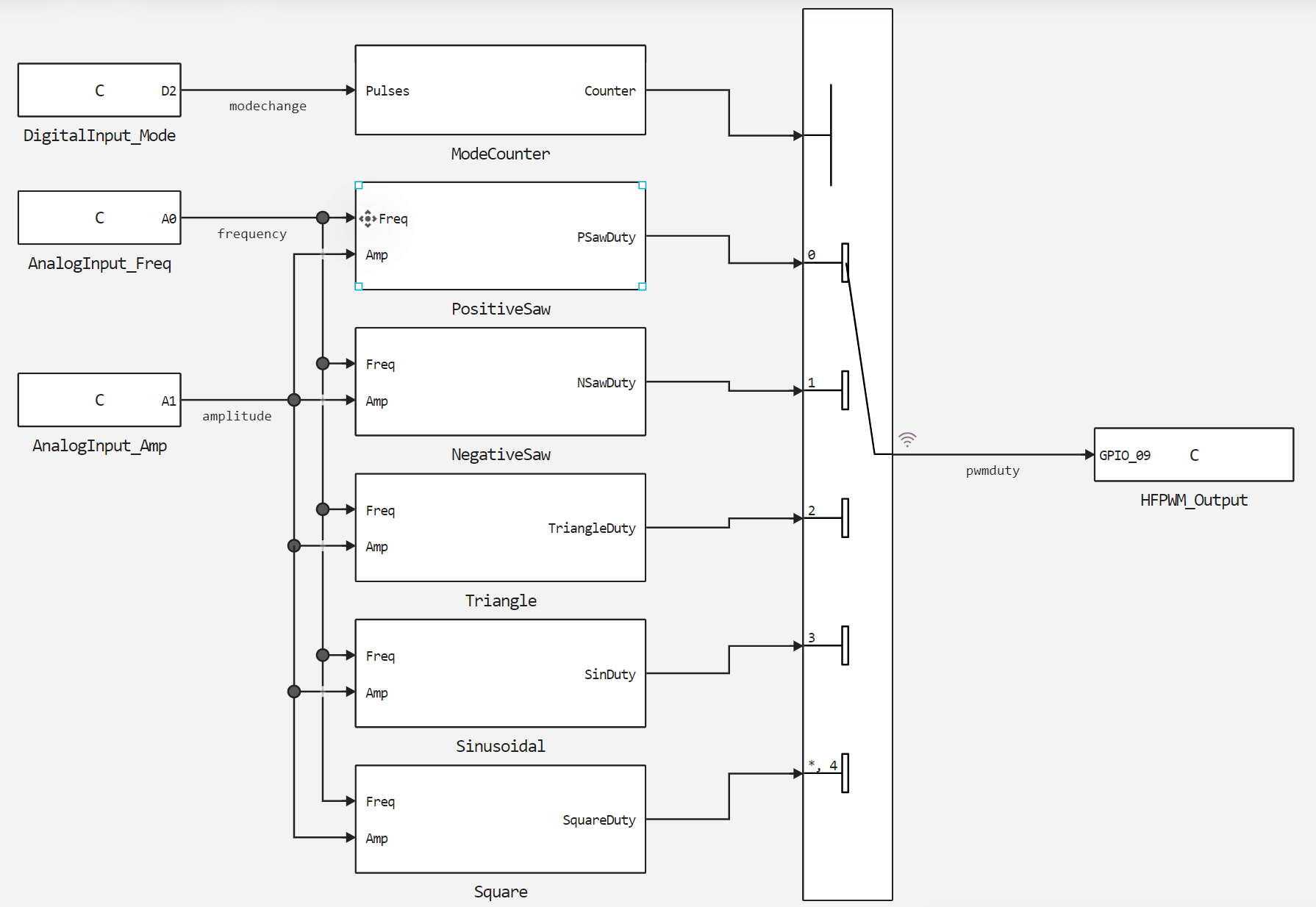
Algorithms for calculating the five specified waveforms are defined in subsystems: PositiveSaw - sawtooth with a positive slope, NegativeSaw - sawtooth with a negative slope, Triangle - triangular, Sinusoidal - sinusoidal and Square - a meander with a borehole of 50%. The block is used to switch between the output waveform algorithms Multiport Switch, which is controlled from the subsystem ModeCounter. In the subsystem ModeCounter The negative edge of the input signal is highlighted and the number of keystrokes is counted.
Thus, when modeling in Engee, the output signal with constant frequency and amplitude settings will periodically switch between the specified waveforms.
Simulation results
Download and execute the created model:
Pkg.add(["WAV"])
if "arduino_dds" in [m.name for m in engee.get_all_models()]
    m = engee.open( "arduino_dds" );
else
    m = engee.load( "$(@__DIR__)/arduino_dds.engee" );
end

data = engee.run(m);
From the obtained model data, we will plot the generated signal.:
using Plots
plotlyjs()
plot(data["pwmduty"].time, data["pwmduty"].value,
    legend=false, size=(900,300), lw=2, st=:step)
xlabel!("Time, seconds")
ylabel!("Meaning")
As you can see, approximately every 0.2 seconds the output signal changes its shape.
Generating code for Arduino
To upload to Arduino, you need to generate code from the developed model.:
engee.generate_code( "$(@__DIR__)/arduino_dds.engee",
                     "$(@__DIR__)/arduino_dds_code")
We will connect the files generated in the specified directory in the user sketch. arduino_dds.ino. Download these files and upload them to the Arduino MEGA using the Arduino IDE.
The attached sketch defines macros and global variables, adds custom generated files and third-party libraries, and calls the initialization and cyclic calculation functions of the model. The sketch also contains comments to explain how the code works.
Running the program on Arduino
After successfully compiling and uploading the sketch to the target device, we will connect a Hantec DSO digital oscilloscope at the output of the RC filter and capture the shape of the generated signal. The measurement experiment shows switching between the generated shapes, followed by the generation of a sawtooth signal with an adjustable frequency, and then with an adjustable amplitude.
To make the DDS model more representative, a speaker was connected to the output of the RC circuit, and the resulting sound was recorded in a file. arduino_dds_audio.wav. The next code cell allows you to upload the received audio file to the script and play it back. Play the audio track to make sure that the developed model is working properly. It records sound when the output waveform is sequentially switched, and then the frequency and amplitude of the sawtooth signal are adjusted with a positive slope.
using WAV, Base64
x, fs = wavread( "$(@__DIR__)/arduino_dds_audio.wav" );

buf = IOBuffer();
wavwrite(x, buf; Fs=fs);
data = base64encode(unsafe_string(pointer(buf.data), buf.size));
markup = """<audio controls="controls" {autoplay}>
              <source src="data:audio/wav;base64,$data" type="audio/wav" />
              Your browser does not support the audio element.
              </audio>"""
display( "text/html", markup );
Conclusion
In this demo, a model of direct digital signal synthesis with adjustable frequency and amplitude was developed, as well as with the ability to switch the waveform between sawtooth positive and negative, triangular, sinusoidal and meander. The results of the simulation in Engee and the execution on the target device are successful and have shown their identity.