Code generation for Milander 1986VE91T (Running Lights)
Introduction
In this example, we consider the generation of code from the Engee model for the 1986VE91T microcontroller from PKK Milander JSC. The model reproduces the operation of the "running lights" on the microcontroller's debugging board, the project is assembled in the Keil MKVISION environment, and the executable code is loaded through the J-Link debugger.
Hardware part
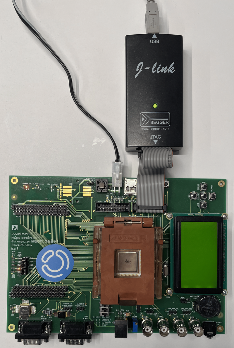
The target device is a microcontroller from PKK Milander JSC 1986ВЕ91Т (MDR32F9Q1). The example uses debugging модуль for chips 1986VE91T, 1986VE94T (version 5):
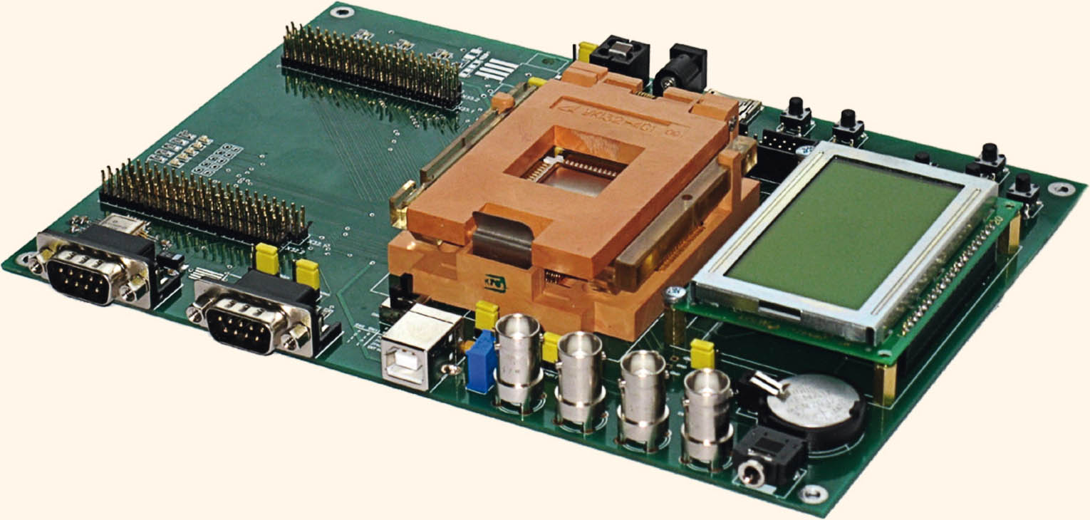
The example tests the operation of digital outputs. PORT_Pin_10 - PORT_Pin_14 the port PORTD microcontrollers that are connected to LEDs VD5 - VD9 on the debugging board. To test the operation, we will reproduce the "running fire" - the sequential switching on and off of LEDs. The turn-on time of each LED is set to 100 ms.
Description of the model
The example model - mdr32f9q1_running_lights.engee. The duration of the high-level signal output to the digital outputs is set in the model by the block period_msec.
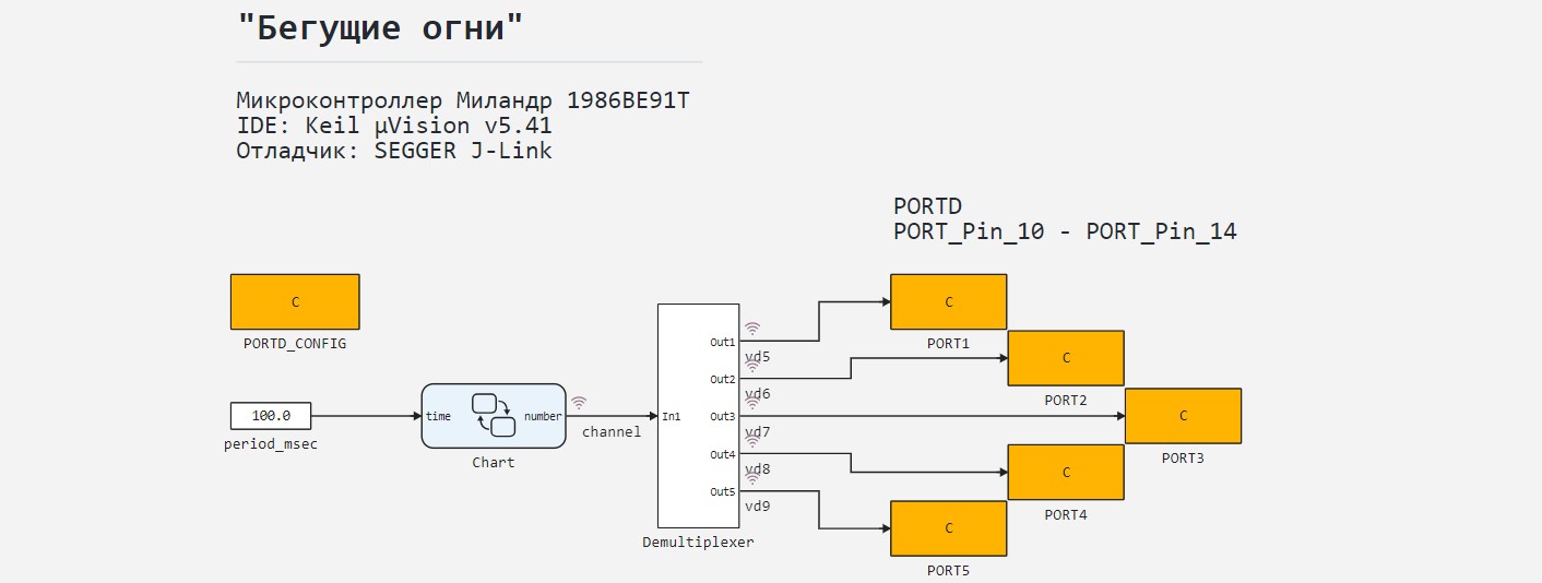
The block Chart reproduces the algorithm for changing the number of the output LED in order with a given period. Block Demultiplexer according to the number of the output LED, it outputs a unit to the corresponding output port. The finite state machine implemented by the block Chart, includes five states that are cyclically alternately activated.
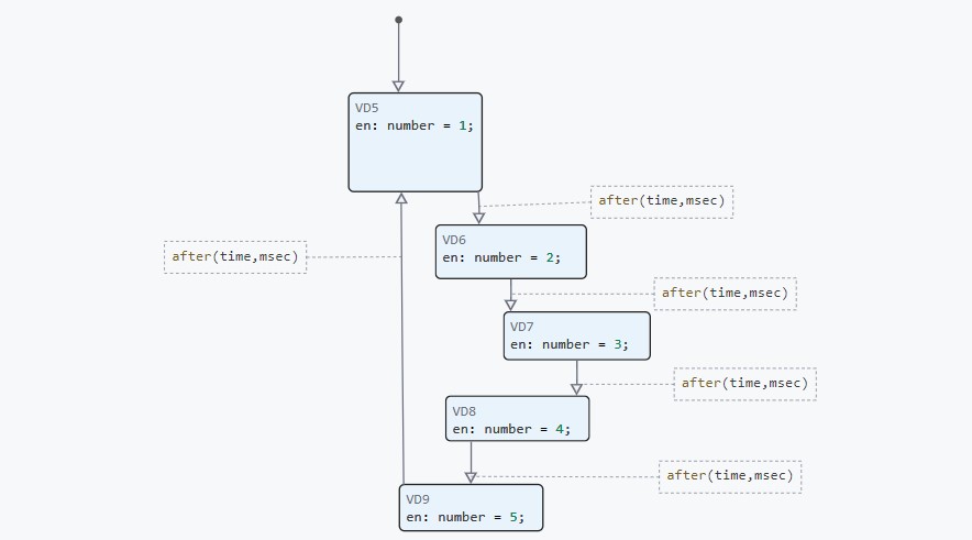
For the transition between the states of a finite automaton, temporal логика.
Peripheral Blocks
Blocks PORTD_CONFIG and PORT1 - PORT5 The C code is added to the model to work with the controller's peripherals. In order to add the lines with the necessary header files to the generated code, in the tab Build options the block PORTD_CONFIG the names and path of the header files to be connected are spelled out. The files themselves do not contain any code and are not used in modeling. When building the project, the plug-in files will be added from the support package for the microcontroller.
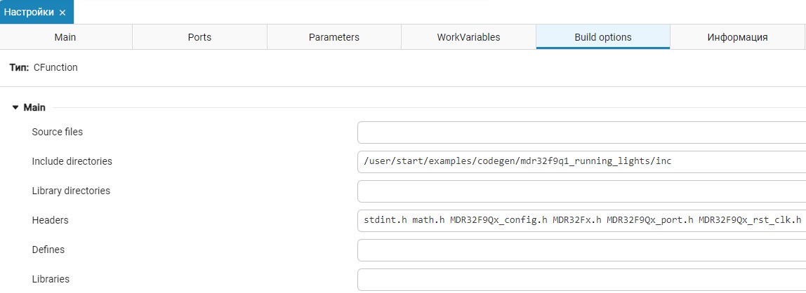
Block PORTD_CONFIG adds to the code generated from the model with functions for initializing ports used in the project, and blocks PORT1 - PORT5 - a code with functions for setting and resetting the active state of the corresponding digital pins.
The contents of the code cells of the peripheral blocks are "wrapped" in conditional preprocessor directives:
#if defined ( USE_MDR1986VE9x )
    // пользовательский код
#endif
This allows you to execute code from blocks only on certain target devices, ignoring it, for example, when modeling in Engee.
Simulation results
Download and execute the example model:
# @markdown **Software modeling management:**
# @markdown Requires you to enter only the model name
имя_модели = "mdr32f9q1_running_lights" # @param {type:"string"}
if the model name is in [m.name for m in engee.get_all_models()]
    model = engee.open( model name );
else
    модель = engee.load( "$(@__DIR__)/"*имя_модели*".engee" );
end
data = engee.run(model);
Let's plot the output variables. The signals of single pulses through the channels are scaled for clarity.:
gr(size = (900,400))
plot(данные["channel"].time, [данные["channel"].value, 1.05.*данные["vd5"].value,
     1.1.*данные["vd6"].value, 1.15.*данные["vd7"].value, 1.2.*данные["vd8"].value, 1.25.*данные["vd9"].value,];
     label=[:none "vd5" "vd6" "vd7" "vd8" "vd9"], title="Running lights", st = :step)
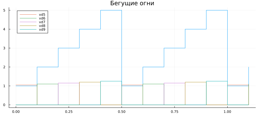
As can be seen from the graphs, the finite state machine and the demultiplexer work out a given algorithm, sequentially forming pulses into five channels with a given duration.
Code generation
Let's generate the code from the developed model.
# @markdown **Code generation:**
# @markdown A folder for the code generation results will be created in the script folder:
папка = "code" # @param {type:"string"}

# @markdown Code generation for the subsystem:
включить = false # @param {type:"boolean"}
if(enable)
    подсистема = "" # @param {type:"string"}
    engee.generate_code( "$(@__DIR__)/"*имя_модели*".engee", "$(@__DIR__)/"*папка;
                     subsystem_name = subsystem)
else
    engee.generate_code( "$(@__DIR__)/"*имя_модели*".engee", "$(@__DIR__)/"*папка)
end

# @markdown Generate `main.c'?
использовать = false # @param {type:"boolean"}

if (!use)
    cd("$(@__DIR__)/"*папка)
    rm("main.c")
end
Since the project will use a ready-made main.c to eliminate confusion, the code cell above deletes the template generated from the model main.c. Ready main.c and the files generated from the model now need to be added to the Keil mkvision development environment project.
The composition of the project
To work with the microcontroller in a development environment, you need to install a support package. For this example, we used an unofficial support package.
The following are the standard steps when working in Keilvision. - create a project, add source files for the necessary peripherals and header files for device configuration, as well as configure the collector and debugger. After that, download the sample files from the folder \code, and also main.c and add them to the Keil project.
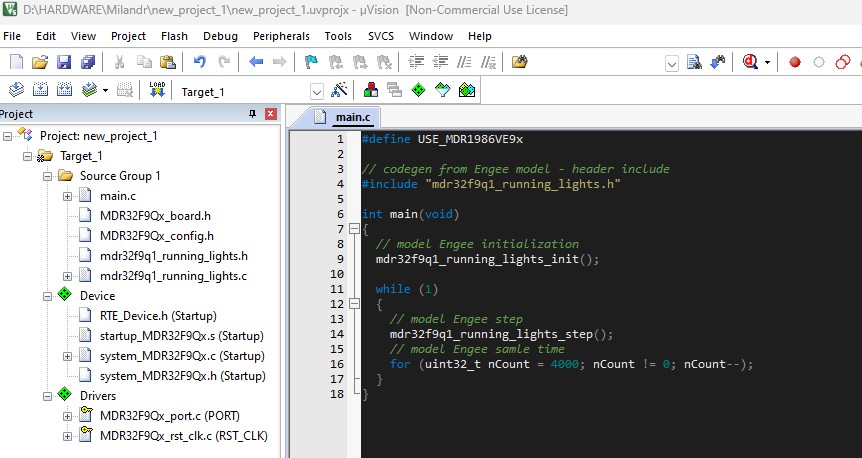
Next, you can build the project and download/debug the code.
Building the project and uploading the code
Let's build the Keil project, after which a similar message should be displayed in the environment terminal.:
Build started: Project: new_project_1
*** Using Compiler 'V6.22', folder: 'C:\Users\engeeuser\AppData\Local\Keil_v5\ARM\ARMCLANG\Bin'
Build target 'Target_1'
compiling main.c...
mdr32f9q1_running_lights.c(49): warning: variable 'seq' is uninitialized when used here [-Wuninitialized]
   49 |         cfunc_symbols->seq = seq;
      |                              ^~~
mdr32f9q1_running_lights.c(44): note: initialize the variable 'seq' to silence this warning
   44 |         int8_t seq;
      |                   ^
      |                    = '\0'
mdr32f9q1_running_lights.c(291): warning: comparison of integers of different signs: 'int64_t' (aka 'long long') and 'uint64_t' (aka 'unsigned long long') [-Wsign-compare]
  291 |         return counter * numerator >= (uint64_t)ceil(condition * denominator);
      |                ~~~~~~~~~~~~~~~~~~~ ^  ~~~~~~~~~~~~~~~~~~~~~~~~~~~~~~~~~~~~~~~
mdr32f9q1_running_lights.c(338): warning: unused variable 'seq' [-Wunused-variable]
  338 |                 double seq = PORTD_CONFIG_cfunc_symbols.seq;
      |                        ^~~
mdr32f9q1_running_lights.c(351): warning: variable 'Chart_selector' set but not used [-Wunused-but-set-variable]
  351 |                 int Chart_selector;
      |                     ^
4 warnings generated.
compiling mdr32f9q1_running_lights.c...
linking...
Program Size: Code=5264 RO-data=224 RW-data=16 ZI-data=1672
".\Objects\new_project_1.axf" - 0 Error(s), 4 Warning(s).
Build Time Elapsed:  00:00:00
The assembly went without errors, let's move on to uploading the code to the microcontroller. Connect the board's power supply and the JTAG debugger. In this example, it is [SEGGER J-link](https://www.segger.com/downloads/jlink /).
If the executable code is successfully loaded into the microcontroller, a similar message will be displayed on the environment's command line.:
Load "D:\\HARDWARE\\Milandr\\new_project_1\\Objects\\new_project_1.axf"
* JLink Info: Device "CORTEX-M3" selected.
Set JLink Project File to "D:\HARDWARE\Milandr\new_project_1\JLinkSettings.ini"
* JLink Info: Device "CORTEX-M3" selected.

JLink info:
------------
DLL: V8.12a, compiled Jan  9 2025 14:34:24
Firmware: J-Link ARM V8 compiled Nov 28 2014 13:44:46
Hardware: V8.00
Feature(s) : RDI,FlashDL,FlashBP,JFlash,GDB

* JLink Info: Found SW-DP with ID 0x2BA01477
* JLink Info: DPv0 detected
* JLink Info: CoreSight SoC-400 or earlier
* JLink Info: Scanning AP map to find all available APs
* JLink Info: AP[1]: Stopped AP scan as end of AP map has been reached
* JLink Info: AP[0]: AHB-AP (IDR: 0x24770011, ADDR: 0x00000000)
* JLink Info: Iterating through AP map to find AHB-AP to use
* JLink Info: AP[0]: Core found
* JLink Info: AP[0]: AHB-AP ROM base: 0xE00FF000
* JLink Info: CPUID register: 0x412FC230. Implementer code: 0x41 (ARM)
* JLink Info: Found Cortex-M3 r2p0, Little endian.
* JLink Info: FPUnit: 6 code (BP) slots and 2 literal slots
* JLink Info: CoreSight components:
* JLink Info: ROMTbl[0] @ E00FF000
* JLink Info: [0][0]: E000E000 CID B105E00D PID 002BB000 SCS
* JLink Info: [0][1]: E0001000 CID B105E00D PID 002BB002 DWT
* JLink Info: [0][2]: E0002000 CID B105E00D PID 002BB003 FPB
* JLink Info: [0][3]: E0000000 CID B105E00D PID 002BB001 ITM
* JLink Info: [0][4]: E0040000 CID B105900D PID 002BB923 TPIU-Lite
ROMTableAddr = 0xE00FF000
* JLink Info: Reset type: NORMAL (https://wiki.segger.com/J-Link_Reset_Strategies)
* JLink Info: Reset: Halt core after reset via DEMCR.VC_CORERESET.
* JLink Info: Reset: Reset device via AIRCR.SYSRESETREQ.

Target info:
------------
Device: MDR1986BE91
VTarget = 3.319V
State of Pins:
TCK: 1, TDI: 1, TDO: 0, TMS: 1, TRES: 1, TRST: 1
Hardware-Breakpoints: 6
Software-Breakpoints: 8192
Watchpoints:          4
JTAG speed: 2000 kHz

* JLink Info: Memory map 'after startup completion point' is active
Full Chip Erase Done.
Programming Done.
Verify OK.
* JLink Info: Memory map 'before startup completion point' is active
* JLink Info: Reset type: NORMAL (https://wiki.segger.com/J-Link_Reset_Strategies)
* JLink Info: Reset: Halt core after reset via DEMCR.VC_CORERESET.
* JLink Info: Reset: Reset device via AIRCR.SYSRESETREQ.
* JLink Info: Memory map 'after startup completion point' is active
Application running ...
Flash Load finished at 10:40:49
Executing code on a microcontroller
After downloading, the code runs automatically on the controller, as can be seen from the running lights on the board.:
The uploaded code executes the algorithm specified by the Engee model.
Conclusion
In this example, we have developed an Engee model that reproduces the "running lights" algorithm using the [Engee finite state machine library] (https://engee.com/helpcenter/stable/en/state-machines.html ) and temporal операторов . generated the code from the model and tested its operation on the Milander 1986VE91T microcontroller, assembling the project and uploading it to the device from Keil mkvision environments.