Building truth tables, Boolean schemes, and expressions
In this demo, we will show how to create a discrete model for calculating output signals from a truth table and compare it with a model created from logic elements.
Description of the model
Let's create a model that converts a set of input bits into an output signal generated according to the following truth table:
| A | B | C | Y |
|---|---|---|---|
| 0 | 0 | 0 | 0 |
| 0 | 0 | 1 | 0 |
| 0 | 1 | 0 | 1 |
| 0 | 1 | 1 | 0 |
| 1 | 0 | 0 | 1 |
| 1 | 0 | 1 | 0 |
| 1 | 1 | 0 | 1 |
| 1 | 1 | 1 | 0 |
The truth table can be set in many different ways, for example by using a code placed inside a block. Engee Function.
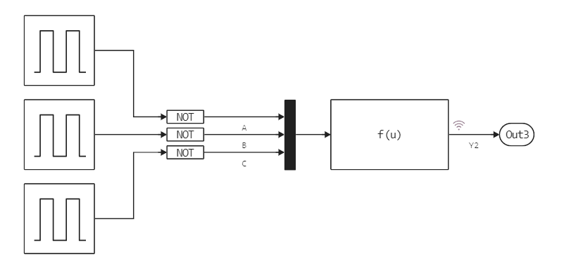
The input signals are generated using pulse generators Pulse Generator for each subsequent generator , the pulse period is divided by 2 ("junior" has a period 1 с, next 2 с, "senior" – 4 с) . By default, all generators start at the top pulse level at time zero (specified in the parameter Amplitude). The usual form for truth tables implies that the enumeration of signals begins at the lower level. In order not to change the phase of each generator, we use the operation Not to each input channel (using an appropriately configured block Logical Operator).
The sampling step of the model is 0.5. In one full period, each generator outputs both pulse values – upper and lower, with a fill factor of 50%. And so we get the following model:
Inside the block, the truth table is described by the following code:
function (c::Block)(t::Real, A, B, C)
    if     A == 0 && B == 0 && C == 0 return 0;
    elseif A == 0 && B == 0 && C == 1 return 0;
    elseif A == 0 && B == 1 && C == 0 return 1;
    elseif A == 0 && B == 1 && C == 1 return 0;
    elseif A == 1 && B == 0 && C == 0 return 1;
    elseif A == 1 && B == 0 && C == 1 return 0;
    elseif A == 1 && B == 1 && C == 0 return 1;
    elseif A == 1 && B == 1 && C == 1 return 0;
    else return 0; end;
end
We can create the same scheme using the logical elements AND, OR, NOT.
Our truth table corresponds to the equation described by the formula ). It is easy to implement with the help of several blocks. Logical Operator.
.png)
Either by using the expression (u[1] || u[2]) && !u[3] inside the block Fcn.
.png)
Launching the model
Let's run the model using software control commands:
modelName = "truth_tables"
# If the model is not open yet, we will upload it from the file
if modelName ∉ [m.name for m in engee.get_all_models()] engee.load( "$(@__DIR__)/$modelName.engee"); end;
data = engee.run( modelName )
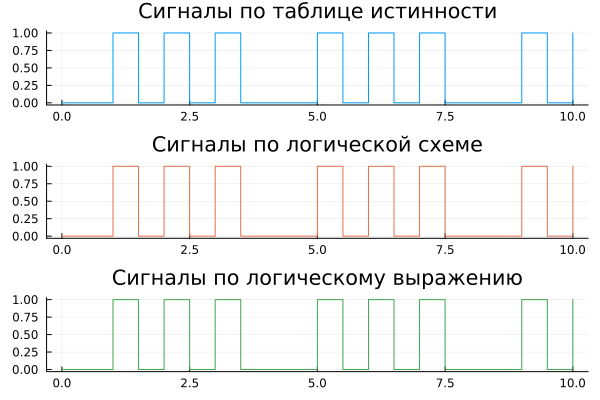
And we visualize the result. If the transformation of the truth table into a logical circuit is performed correctly, we should get three identical graphs.:
gr()

plot(
    plot( data["Y"].time, data["Y"].value, st=:step, lc=1, leg=false, title="Truth table signals" ),
    plot( data["Y1"].time, data["Y1"].value, st=:step, lc=2, leg=false, title="Signals according to a logical scheme" ),
    plot( data["Y1"].time, data["Y2"].value, st=:step, lc=3, leg=false, title="Logical expression signals" ),
    layout=(3,1)
)
Conclusion
We have built several simple models that can be used to study microelectronics or to create an environment for testing digital devices.