Using tires
In this example, we will analyze the possibilities of using multiple signal buses to visually simplify models.
The model is shown in the figure below. The purpose of this model is to combine three signals into one bus and convert them inside the subsystem.
A sinusoidal signal is applied to the input, the frequency of which varies linearly with time, a sinusoid with a constant frequency, and a switching signal from 0 to 1.
The following figure shows the internal structure of the subsystem. In it, we decompose the bus into three separate signals, after which we double the first signal, increase the frequency 10 times for the second, and reverse all input values for the third. After that, we reassemble the tire, but with new names. It is also worth clarifying that the signals inside the bus can be of different lengths and have different sampling rates.
.png)
The figure below shows the interface of the Bus Selector block, which allows us to select the signals we need from the bus.
.png)
Next, let's compare the input and output values for the signals that were manipulated.
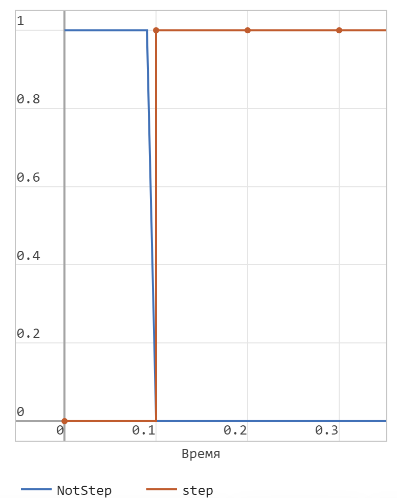
.png) In the first case, we see that the value of the output signal is the negative of the input.
In the first case, we see that the value of the output signal is the negative of the input.
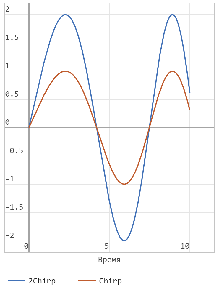 In the second case, we see that the amplitude of the output signal is twice as large as that of the input signal.
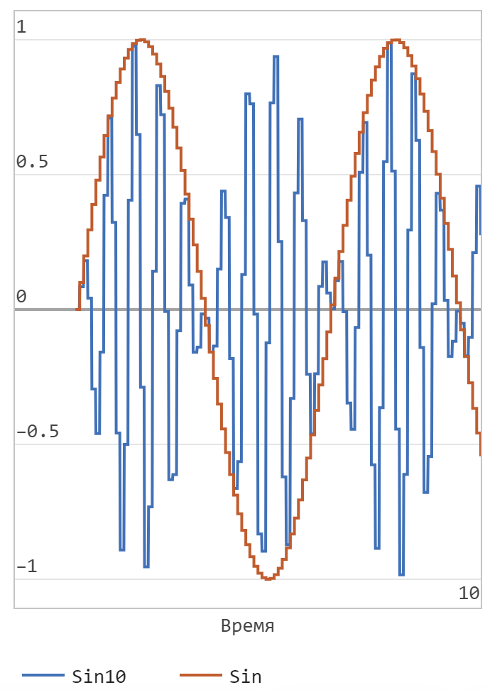 In the third case, we see that the frequency of the output sine wave is ten times higher than that of the input.
Conclusion
Our experiments on signals have shown that working with buses makes it quite easy to interact with any number of signals. If necessary, we can always find them by their pre-defined name in the list of bus signals. This greatly simplifies working with projects that have a large number of signals transmitted between different subsystems of the model.