The JK trigger model
In this example, we will show how to model a JK trigger using components from the basic palette of the block library.
Description of the model
This model shows how to assemble a JK trigger from logical components (blocks Logic) and delay blocks (UnitDelay). The trigger updates its state with each pulse of the clocking signal (block PulseGenerator), so based on this model, it is possible to show how the input signal is formed depending on the switching of inputs J and K.
If the input switches of the model are in the initial state ("up" position) Both inputs of the JK trigger are set to 1, and then the output state of the trigger switches on each descending edge of the clocking signal (trailing edge).
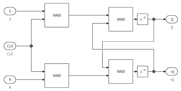
There are two SR triggers inside the JK trigger subsystem:
.png)
SR triggers look like this (all logical elements are implemented using blocks Logic):
.png)
Upper block
Unit Delaybefore exitingQinitialized with the value-1, the lower output is initialized to zero.
The work of the model
We will upload (if the model is not open yet) and execute the model using the software management tools.:
if "jk_trigger" ∉ getfield.(engee.get_all_models(), :name)
    engee.load( "$(@__DIR__)/jk_trigger.engee");
end;

data = engee.run( "jk_trigger" )
Let's plot the schedules of the model in a state when both inputs are set to the upper position.
gr()

plot(
    plot( data["CLK"].time,
        [ data["CLK"].value, data["J"].value, data["K"].value ],
          lc=[1 2 5], lw=2, titlefont=font(9), linestyle=[:solid :solid :dash], legend = :outerright,
          label=["CLK" "J" "K"], title="Signals at the input of the synchronous JK trigger"),
    plot( data["CLK"].time,
          [ data["Q"].value, data["~Q"].value ],
          lc=[3 4], lw=2, legend = :outerright, titlefont=font(9),
          label=["Q" "~Q"], title="Signals at the output of the synchronous JK trigger"),
    layout=(2,1)
)
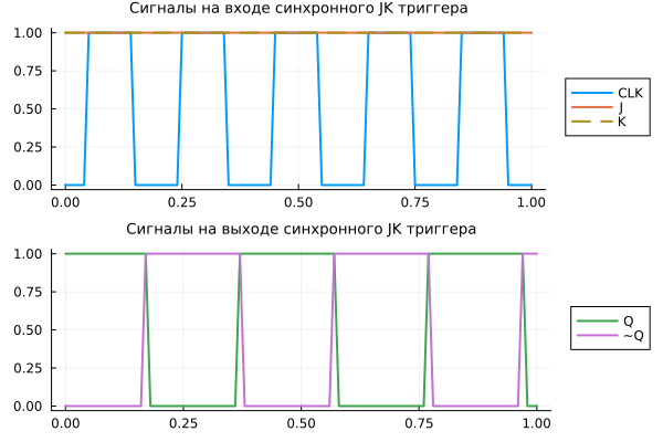
When is the clocking signal CLK In the upper position, the first RS trigger is activated, but the second is not. Signals J and K At this point, the value of the first trigger can be changed, while the value of the second trigger is frozen. If you change the input parameters by setting J=1 and K=0, then the output of the first trigger Q it is set to 1, but the input of the second one does not change.
As soon as the clocking signal CLK switches to the lower position, the second RS trigger is activated, and the first one is turned off. The second trigger assumes the state of the first one, its output values are now equal to the output values of the first one at the previous stage (the first trigger retains the previous state). The output of the first trigger was Q=0 therefore , the second trigger gets an input S=1 and R=0, and the output of the second trigger becomes Q=1. But since the input trigger is disabled, changing the input signals does not change its state.
And when is the clocking signal CLK it switches to the upper position again, the first trigger is activated, and the second one is deactivated. Outputs JK the triggers do not change on the leading edge because the second trigger is disabled and does not change its state.
Conclusion
We have studied the model of a JK trigger, a device capable of staying in one of two stable states for a long time and alternating them under the influence of external signals.
A more detailed model could be assembled from CMOS logic blocks, but in its current form it perfectly shows the principle of operation of the JK trigger.