The DSP task using the sigma-delta analog-to-digital converter model as an example
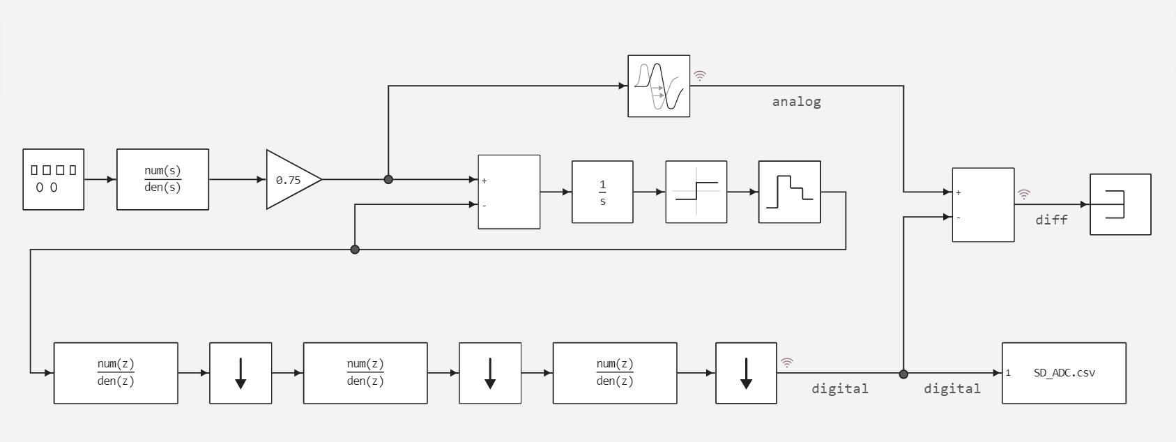
This example implements the Sigma-Delta analog-to-digital converter (Sigma-Delta ADC) model, which uses the delta-sigma modulation method to achieve high accuracy and resolution in measuring analog signals. It is widely used in various applications requiring high measurement accuracy, such as audio, measuring sensors, etc. (model sigma_delta_adc.engee):
Next, in this example, the work of Sigma-Delta ADC in Simulink and Engee is analyzed, and the results of the work of the two development environments are compared.
First you need to connect the libraries:
Pkg.add(["Statistics", "CSV"])
# Connecting libraries
using Plots
using CSV
using DataFrames
using Statistics
plotlyjs();
Launching a model implemented in the Engee development environment.
modelName = "sigma_delta_adc"
SDC_model = modelName in [m.name for m in engee.get_all_models()] ? engee.open( modelName ) : engee.load( "$(@__DIR__)/$(modelName).engee");

results = engee.run( modelName )
Visualization of model outputs
SD_ADC_res_t = results["SD_ADC"].time;
SD_ADC_res_d = results["SD_ADC"].value;
p_adc_da_sl = plot(SD_ADC_res_t, SD_ADC_res_d, legend = false) # Plotting a graph
plot!(title = "Simulation results in Engee", ylabel = "Digital signal", xlabel="Time, c") # The signature of the axes and the title of the graph
Simulation results in Simulink:
using MATLAB # Connecting the MATLAB core
mat"cd /user/start/examples/dsp/sigma_delta_adc"
mat"""
    out = sim('sigma_delta_adc');
    sig = getElement(out.yout,1);
    $DA_times = sig.Values.Time;
    $DA_values = sig.Values.Data;
    """; # Запуск Simulink
p_adc_da_sl = plot(DA_times, DA_values, legend = false)
plot!(title = "Simulation results in Simulink", ylabel = "Digital signal", xlabel="Time, c")
The models use a variable-pitch solver. It is necessary to "synchronize" the signals. First, let's put the graphs on top of each other.:
plot(SD_ADC_res_t ,SD_ADC_res_d, label = "Engee")
plot!(title = "Comparison of simulation results")
plot!(DA_times, DA_values, label = "Simulink")
# plot!(label = ["Engee" "Simulink"])
plot!(legend = :outertopright,ylabel = "Digital signal", xlabel="Time, c")
We find the intersection of two vectors with the simulation time:
# 1. Check that the array lengths are consistent
if length(SD_ADC_res_t) != length(SD_ADC_res_d)
    error("The sizes of SD_ADC_res_t and SD_ADC_res_d do not match!")
end

# 2. Trim DA_times/DA_values to the length of SD_ADC_res_t (if necessary)
new_length = min(length(DA_times), length(SD_ADC_res_t))
DA_times = DA_times[1:new_length]
DA_values = DA_values[1:new_length];

# 3. We find the intersection of timestamps
common_times = intersect(DA_times, SD_ADC_res_t)

if isempty(common_times)
    error("There are no matching timestamps between DA_times and SD_ADC_res_t!")
end
Then, you need to get the values in common points.
# 4. We find the indexes of matching elements (using integer indexes)
SD_ADC_d = collect(SD_ADC_res_d).value
SD_ADC_t = collect(SD_ADC_res_t).time

da_idx = findall(t -> t in common_times, DA_times)
sd_idx = findall(t -> t in common_times, SD_ADC_t)

# 5. Make sure that the indexes correspond to each other in time.
if !all(DA_times[da_idx] .== SD_ADC_t[sd_idx])
    error("Mismatch of timestamps after indexing!")
end

# 6. Extracting the data
sd_comp_t = DA_times[da_idx]
sd_comp_sl = DA_values[da_idx]
sd_comp_en = SD_ADC_d[sd_idx]

# 7. Check the result
@assert length(sd_comp_t) == length(sd_comp_sl) == length(sd_comp_en) "The sizes of the output arrays do not match!"
println("Successfully processed $(length(sd_comp_t)) matching points")
Now we can correctly compare the results of Simulink and Engee.:
adc_abs_tol = sd_comp_sl - sd_comp_en;
mean_adc_tol = abs(mean(adc_abs_tol));
adc_rel_tol = (sd_comp_sl - sd_comp_en)./sd_comp_sl;
mean_adc_tol_rel = abs(mean(filter(!isnan,adc_rel_tol)));
println("Average absolute error of calculations:", mean_adc_tol);
println("Average relative error of calculations, %:", abs(mean_adc_tol_rel*100));
engee.close( modelName, force=true);
Conclusion
To summarize, this example implements a sigma-delta analog-to-digital converter model. Based on this example, we can draw several conclusions:
- Engee is not inferior in accuracy to Simulink
- Engee allows you to use the MOS, and thanks to the large library of blocks, we have the opportunity to implement a large functionality of blocks.
- And also, if the functionality of Engee is insufficient, we can use the functionality of MATLAB inside Engee