Uninterruptible power supply
Description of the model
This example presents a model of a linearly interactive uninterruptible power supply (UPS) based on a bidirectional inverter with an electric power storage device in the form of a supercapacitor. The inverter has a rated power of 2.4 MW. The UPS is controlled by converting currents and voltages into a dq coordinate system and PI regulators. The capacity of the supercapacitor is 50 F, the rated voltage is 990 V. Synchronization with the external network is performed by the phase-locked frequency unit (PLL).
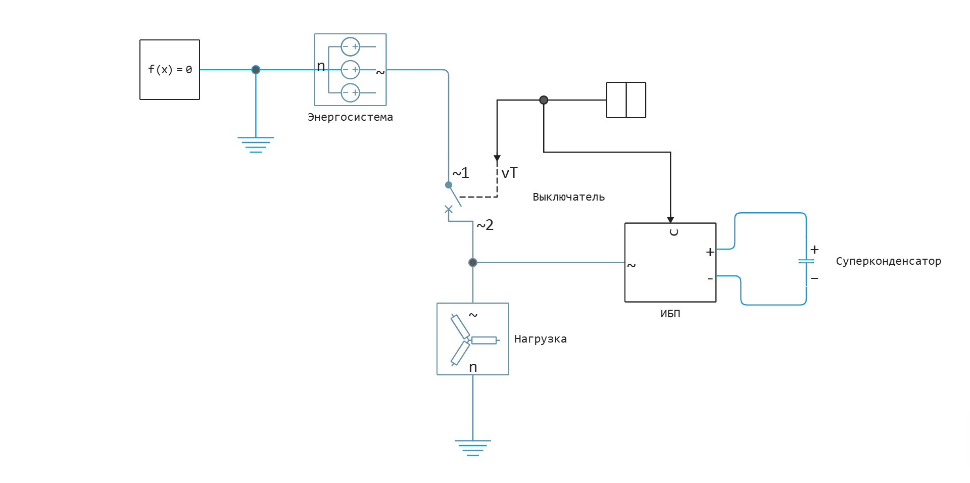
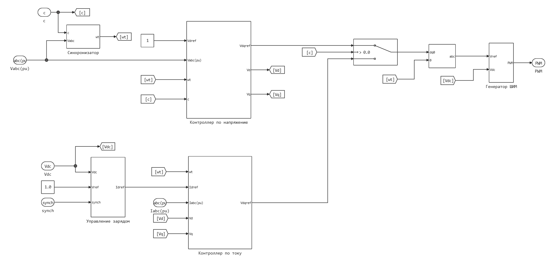
While the UPS is connected to the mains, it maintains the rated voltage on the supercapacitor (current controller is on), when disconnected from the external network, the UPS maintains the rated voltage on the load (voltage controller is on). The control system consists of the following subsystems:
- Synchronizer — contains a PLL block for synchronization with an external network and a 50 Hz angular frequency generator for operation of the inverter in isolated mode. Switching blocks occurs when a signal is sent to disconnect from the external network.
- Charge management — regulates the active power of the inverter to maintain the rated voltage on the supercapacitor in standby mode using a PI controller. The unit turns on when the inverter is connected to the mains.
- Voltage controller — regulates the voltage of the inverter when disconnected from the external network. The operation of the controller is based on the decomposition of voltages into dq components and their subsequent regulation by PI regulators.
- Current controller — controls the inverter in standby mode, i.e. when connected to an external network. The operation of the controller is based on the decomposition of currents into dq components and their subsequent regulation by PI regulators.
- PWM generator — generates PWM signals to control the transistors of the inverter. The principle of operation is based on comparing a triangular reference signal (3 kHz) and a modulating signal (three-phase voltage).
Simulation scenario
The model considers the following scenario:
-
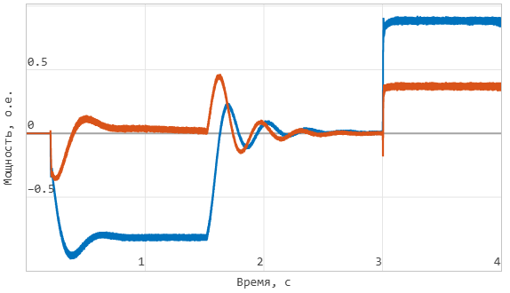
At the moment of 0.2 seconds, the inverter is connected to the mains, the charging of the supercapacitor begins to the rated voltage.
-
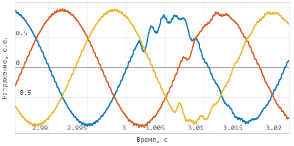
At the moment of 3 seconds, disconnection from the external network occurs, and the UPS switches the load to autonomous power supply.
This scenario allows you to check:
-
Correct charging of the supercapacitor.
-
Smooth switching between modes.
Simulation results
The simulation results are presented below in the form of graphs.
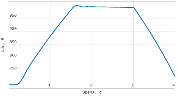
Supercapacitor voltage:
Active and reactive power of the inverter:
Instantaneous voltage at the output of the inverter at the moment of switching to isolated operation:
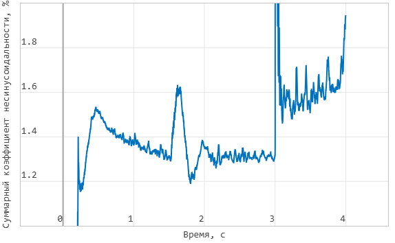
The total coefficient of non-sinusoidal phase A voltage at the output of the inverter: