Zero-sequence directional current protection
Introduction
In this example, the logic of operation of the current directional (non-directional) protection of the zero sequence (hereinafter TNNP) is implemented. The operation of the TNNP is shown in the model of the simplest 220 kV power system.
Description of the model
The scheme and parameters of the power system are presented below:
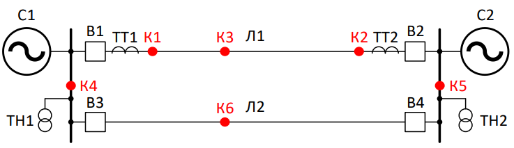
Parameters of the C1 power system:
The active resistance of the direct sequence is 0.393 ohms
The inductive resistance of the direct sequence is 4,276 ohms.
The active resistance of the zero sequence is 0.494 ohms
The inductive resistance of the zero sequence is 4.02 ohms
Equivalent EMF– 230 kV
The EMF phase angle is 10°
Parameters of the C2 power system:
The active resistance of the direct sequence is 4.85 ohms
The inductive resistance of the direct sequence is 25.604 ohms
The active resistance of the zero sequence is 10.607 ohms
The inductive resistance of the zero sequence is 53.347 ohms.
The equivalent EMF is 220 kV
The EMF phase angle is 0°
Parameters of lines L1 and L2:
Length 100 km
The resistivity of a straight line is 0.0958 +j 0.4038 ohms/km
The resistivity of the zero sequence line is 0.3471+ j 1.2432ohms/km
The specific capacity of the direct sequence is 2,642 µsm/km
The specific capacity of the zero sequence is 2,119 µsm/km
Callbacks are set in the model. When opening the model, variables describing the parameters of the lines will be created.:
Z1 = 0.0958 + 0.4038im
Z0 = 0.3471 + 1.2432im
B1 = 2.6424e-6
B0 = 2.119e-6
Description of the developed blocks
Implementation of the TNNP
Current protection of the zero sequence (TNNP) includes:
-
current relay that controls the current value ;
-
power direction relay (PNM), which determines the power direction of the zero sequence.
The presented implementation uses the following trigger logic.
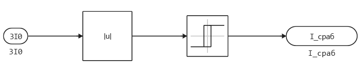
Current relay
The trigger occurs under the condition:
The relay returns when the condition is met:
Current relay in the model:
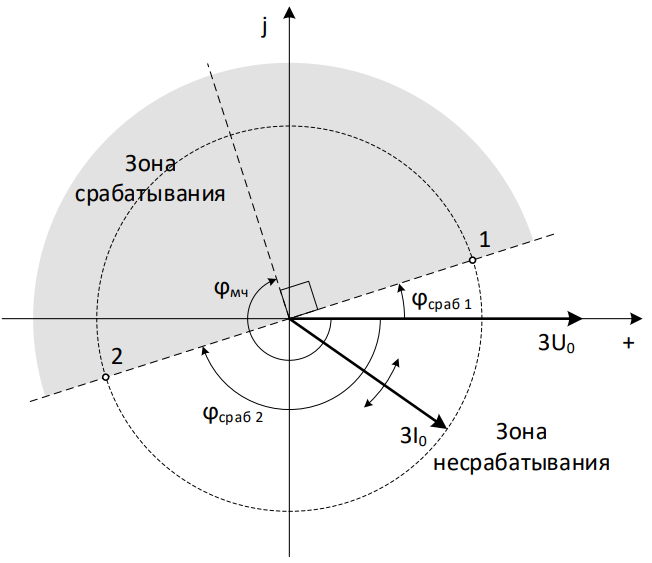
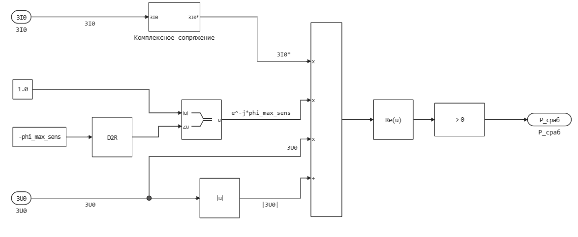
Power direction relay
Triggered occurs under the condition:
where – complex conjugate current of the zero sequence.
Graphical representation of the formula:
Power direction relay in the model:
Implementation of the TNNP in the model:
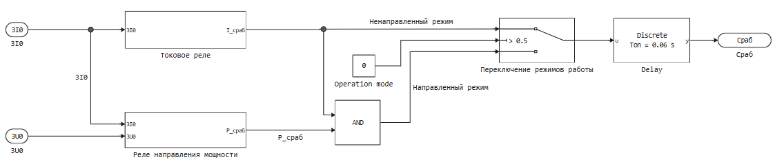
The implementation of protection in the model provides for operation in both directional and non-directional mode. Switching modes is performed by the * "Switching operating modes" block*. The Operation mode parameter is set via the subsystem mask.
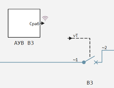
Implementation of AUV
The relay protection kit transmits activation commands to the simplified switch control automation (AUV) unit.
The AUV block models:
-
Trigger delay (switch off time);
-
simulation of the simplest ** automatic re—activation** (APV) - without synchronism control and without line voltage control.
.png)
The Monostable unit captures the impulse to turn off the switch during a non-current pause. The value of the time of the shockless pause is set through the mask of the AUV block.
Constant "Number of APV launches" limits the number of re-inclusions. A single APV is implemented in this model.
There are no protection kits installed on the L-2 line to speed up the simulation. However, the control units of switches B3 and B4 can send commands to turn on and off.
The trigger points are set via the block mask. In the current setting, the parameters simulating a short circuit on L-2 are set for AMV B3 and B4.:
-
switch B3 is switched off by the second stage of the TNNP;
-
Switch B4 is the first stage.
After disconnecting, both switches attempt to turn on again after a shockless pause. The APV attempt is unsuccessful, and the switches are switched off again.
.png)
To disable the L-2 line, you can set the zero parameters in ABV B3 and B4. In this case, the shutdown command is sent to the switches immediately when the simulation starts.
The simulation of a short circuit on the L-1 is performed either by breaking the connection between the AMV and the switch, or by setting the short-circuit moment exceeding the simulation time.
Setting up the TNNP
The first and second stages of zero-sequence current protection are configured in the model. The calculation method used is shown below.
The first stage is detuned from the maximum tripled current of the zero sequence during an earth fault on the busbars of the opposite substation:
where – maximum tripled zero sequence current at the protection installation location;
The second stage of the TNNP must completely cover the protected line. Since in the system under consideration there is only a parallel line in the periphery, it is sufficient to adjust the protection against the minimum tripled current of the zero sequence during an earth fault on the buses of the opposite substation.:
where – minimum tripled zero sequence current at the protection installation location;
The angle of maximum sensitivity of the TNNP power direction relay is determined by the expression:
where – the specific complex resistance of the zero sequence line, Ohms/ km;
TNNP Testing
First, open the model and download it for a quick launch.:
example_path = @__DIR__; # We get the absolute path to the directory containing the current script
cd(example_path); # Go to the example directory

model_name = "ground_directional_overcurrent_relay.engee"
engee.open(model_name); # Opening the model
model = engee.load(model_name); # Download the model for quick access
Let's prepare a model for testing the operation of the L1 protection at point K2 with L2 turned on and run the simulation.:
path = engee.gcm().name # Model name
# Setting the parameters of the short circuit block
t_sc = 0.5 # We set the time of the short circuit and send it to the short circuit block
engee.set_param!(path * "/К2", "temporal" => true,
                "type" => "Single-phase to ground (a-g)")
duration = 10 # Passing the duration parameter to block K3
# Enabling the parallel line. In the AUV, the parameters for the start of a short circuit are set for obviously long simulation durations.
engee.set_param!(path * "/АУВ В3", "t_start" => 10.0)
engee.set_param!(path * "/АУВ В4", "t_start" => 10.0)
results = engee.run(model);
The code below will allow you to check the correctness of the TNNP operation.:
# We will get the simulation results
I0_1 = results["|3I0_1|"].value
Iabc = results["I_1"].value
t = results["|3I0_1|"].time;

# We obtain the setpoint values of the first and second protection stages L1 from the C1 side
I_trip_first = parse(Float64, engee.get_param(path * "/С1: ТНЗНП 1ст Л1", "I_trip"))
I_trip_second = parse(Float64, engee.get_param(path * "/С1: ТНЗНП 2ст Л1", "I_trip"));
# The calculation step is set to 100e-6 in the model.
# The transient process decays in about 0.07 seconds, determine the value of the short-circuit current
index_sc = Int(floor((t_sc + 0.071) * 10^4)) # We get the index for determining the short-circuit current
# Or we get the index this way. This implementation allows you to get an index regardless of the calculation step.
index_sc = findfirst(t .>= t_sc + 0.071)
# We keep the short-circuit current
I_sc = I0_1[index_sc];
# We will get the trigger status from the first and second stages
signal_second_stage = results["S1: TNZNP 1st L1.Srab"].value[index_sc] # By the time the short circuit fades, the 1st stage is already triggered
# The second stage is triggered later
# Receiving the second stage trigger signal
t_second_trip = parse(Float64, engee.get_param(path * "/С1: ТНЗНП 2ст Л1",
                    "t_trip")) + t_sc + 0.02
index_second_trip = findfirst(t .>= t_second_trip)
signal_second_stage = results["S1: TNZNP 2st L1.Srab"].value[index_second_trip];
# If any stage is triggered, we consider that the protection has worked.
 if results["S1: TNZNP 1st L1.Srab"].value[index_sc] || results["S1: TNZNP 2st L1.Srab"].value[index_second_trip]
    trip_status = true
 else
    trip_status = false
 end;
# Let's compare the short-circuit current with the setpoint
if I_sc >= I_trip_first || I_sc >= I_trip_second
    trip_correct = true
else
    trip_correct = false
end;
# Output the results
println("""
The setpoint of the first stage is $I_trip_first and
The setpoint of the second stage is $I_trip_second and
Short-circuit current value: $(round(I_sc, digits=2)) A
Exceeding the current setpoint: $trip_correct
Protection activation: $trip_status
""")
Let's plot the tripled current of the zero sequence for a visual analysis of the protection operation conditions.:
# Plotting the zero sequence current
# We build the main current graph
plot(
    t, I0_1,
    label="3I0_1",
    xlabel="t, c",
    ylabel="I, And",
    title="Current graph 3I0 on the C1 side",
    color=:blue
)

# We add horizontal lines to graphically display the current settings.
hline!([I_trip_first], label="1st stage", linestyle=:dash, color=:red)
hline!([I_trip_second], label="2nd stage", linestyle=:dash, color=:green)
Phase current graphs measured on the C1 side:
I = reduce(hcat, Iabc)' # Транспонируем, чтобы получилась матрица (N×3)

# Building a graph
plot(t, I, lw=2, label=["Phase A" "Phase B" "Phase C"], color=[:orange :green :red])
title!("Graph of phase currents on the C1 side")
xlabel!("Time, c")
ylabel!("Current, A")
Conclusion
This example demonstrates the implementation of the logic of the TNNP operation. A simplified circuit diagram of a power system with several short-circuit points was used to verify the protection's operability. The logic of operation was tested with an internal short circuit at point K2. In this case, the short circuit on the C1 side is switched off by the second stage of the TNNP, and on the C2 side by the first.
Based on the presented blocks, you can independently assemble and configure your own set of protections.