B16 Functional testing program for interlocking in case of voltage failures for 6-35 kV networks
In this example, a test network model is implemented to perform functional blocking tests in case of voltage failures for 6-35 kV networks from Appendix B16 STO 56947007-29.120.70.241-2017. Technical requirements for RPA microprocessor devices. Before testing, the instantaneous values of secondary currents and voltages are calculated on a mathematical model. Calculations are performed for various types of violations (damages) in the secondary TN circuits (short circuits and open circuits), as well as for damage on the primary side. The results of calculating instantaneous values are recorded in a unified Comtrade file according to the standard IEC 60255-24. A separate file is generated for each type of violation.
During the testing process, the Comtrade files generated are converted by the test unit into an analog form and connected to the test device according to the [RETOME] type (https://dynamics.com.ru/production/kompleks-51-61 ).
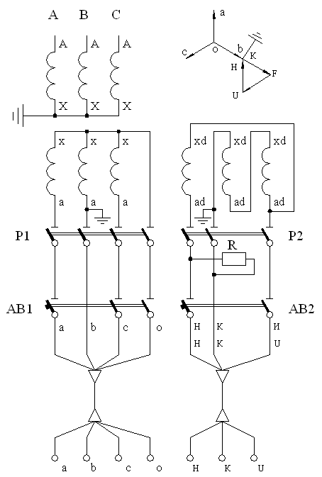
Voltage transformer circuit:
Power system parameters:
The active resistance of the direct sequence is 3.77 ohms
The inductive resistance of the direct sequence is 35.53 ohms
Equivalent EMF – 37.72 kV (Phase A - 99%, Phase B - 101%, Phase C - 100%)
EMF phase angle – 0°
Overhead line parameters:
Length 30 km
The total resistance of a straight line 9 +j is 0.4155 ohms/km
Voltage transformer:
Snom = 1200 VA
The nominal phase voltage of the primary winding is 35/√3 kV
The nominal phase voltage of the main secondary winding is 100/√3 V
The nominal phase voltage of the additional secondary winding is 100/3 V
The total total resistance of TN is 0.1687 ohms
The total active resistance of TN is 0.1089 ohms
The active resistance of the antiresonance resistor is 25 ohms
Main winding circuits:
The resistance of the phase core is 0.0703 ohms
The resistance of the zero core is 0.1406 ohms
The capacity between the cores is 30 nF
Insulation resistance between the cores is 20 mOhm
Additional winding circuits:
The core resistance is 0.293 ohms
The capacity between the cores is 11 nF
Insulation resistance between the cores is 20 mOhm
Secondary load of TN:
Main windings: 100 W – for phase A, 110 W – for phase B and 95 W – for phase C, 50% of the power load is on phase voltages, 50% of the power is on line voltages.
Additional windings:
terminals H and K (UH) – 10 W at a voltage of 100 V
terminals H and U (UHU) – 0.5 W at a voltage of 33.3 V
terminals U and K (UUK) – 0.5 W at a voltage of 33.3 V
Current transformer:
pt= 300/5 A
W1 = 1
W2 = 60
R1 = 0.3 mOhm
X1 = 0 Ohms
R2 = 0.45 ohms
X2 = 0 Ohms
Rh = 1.2 ohms
Formation of COMTRADE files
Functional blocking tests in case of violations in voltage circuits are carried out on the basis of Comtrade format files in which the results of calculating the instantaneous values of currents and voltages from the model are recorded.
COMTRADE files are generated using the To COMTRADE block. A detailed example of using and configuring this block is available in the Community Engee.
To generate the signals, a model is used containing the equivalent of a power system, substation buses with an outgoing power line, a voltage transformer (TN) connected to the buses and a current transformer (TT) of the line, and the instantaneous values of secondary currents and voltages are calculated. The model's appearance:
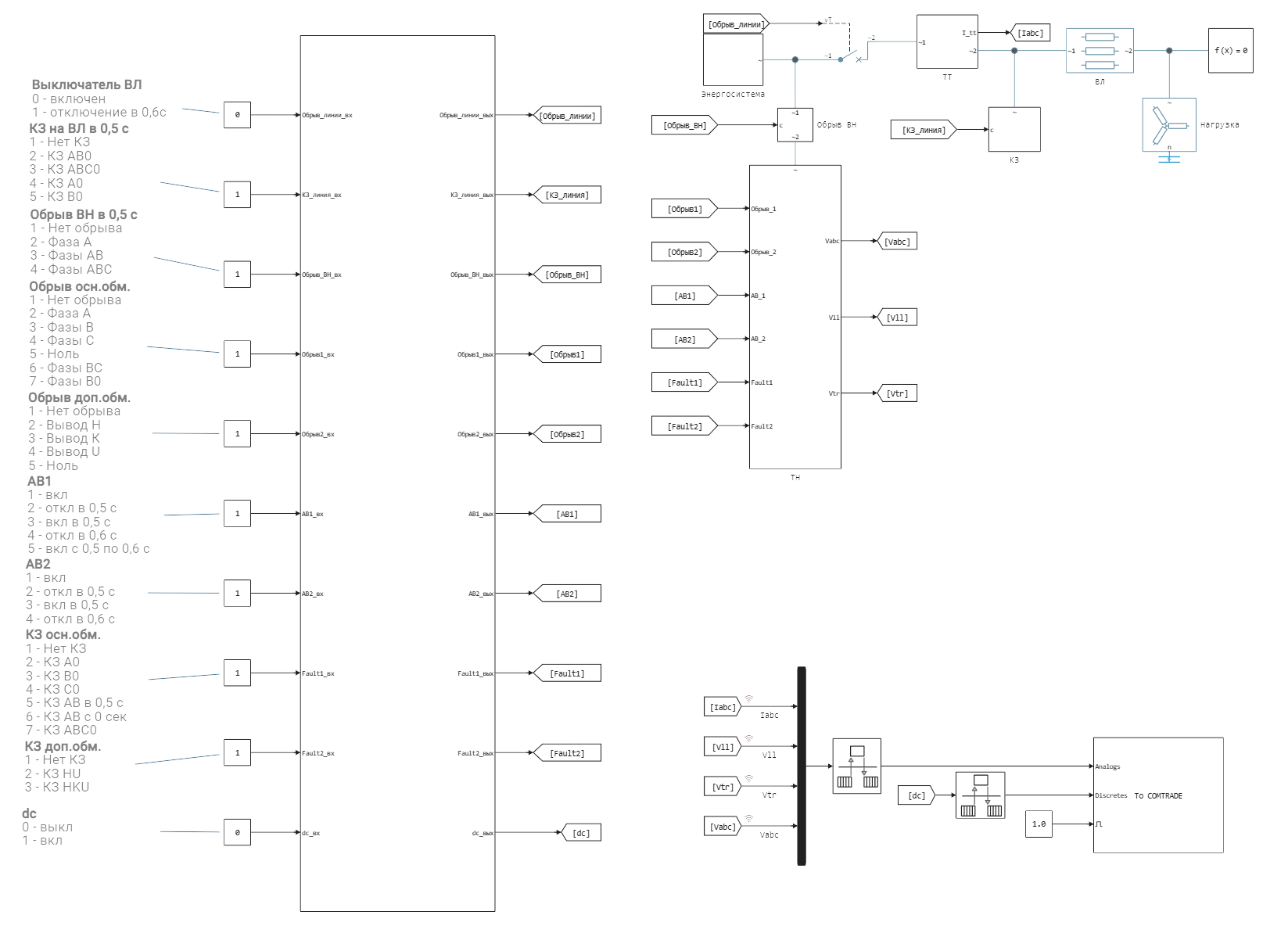
The experiment control unit is implemented in the model, it is located on the left side of the model. To set up the experience, you must independently select the necessary switches in the model by setting the appropriate values of the constants. In the To TRADE block, it is necessary to change the name of the generated files via the Files path parameter in accordance with current experience. After setting up the experience and running the model, the COMTRADE files will be automatically written to the current folder.