Testing of relay protection devices for power lines in transient modes accompanied by current saturation. GOST 70358-2022 model A4.2
Introduction
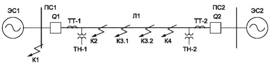
This example shows a model of a 500 kV power system designed to test relay protection devices for compliance with the requirements of GOST 70358-2022 "Requirements for the operation of relay protection devices for power transmission lines of voltage class 110 kV and higher in transient conditions accompanied by saturation of current transformers." The model has been developed in accordance with Appendix A4.2 of the specified standard.
The example also includes a script that programmatically edits the model in accordance with the test program for relay protection devices. The test program is given ** in paragraph A4.3** of GOST. The example demonstrates one experiment for each test of the basic multiplicity and the aperiodic component.
Relay protection devices are tested on real-time simulation devices. But to get acquainted with the example, you can run the model both in Engee and on KPM RHYTHM with the connection and configuration of the device under test.
Description of the model
The parameters and scheme of the model are taken from Appendix A, paragraph 4.2 of the standard.
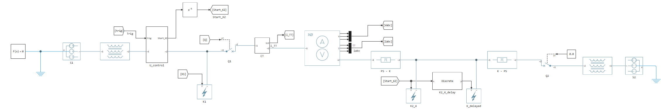
Let's open the model of the energy system:
model_name = "gost_70358_model_A4.engee"
engee.open(model_name); # Opening the model
model = engee.load(model_name); # Download the model for quick access
path = engee.gcm().name; # Model name
Initializing model parameters
The standard requires testing based on the basic parameters and with a change:
- Constant attenuation time of the aperiodic component of the sources (.)
- Multiplicity of the short-circuit current component from the sources ()
First, we initialize the basic parameters of the model.
# Sampling period
SampleTime = 50e-6;
# Basic VAH
V_base = [0 25 50 75 80 85 90 95 99 100 108];
I_base = [0 0.00215 0.0043 0.00675 0.0075 0.00868 0.011 0.02 0.044 0.05 10];
# Current Transformer Parameters (TT)
I1 = 1000
I2 = 1
R2 = 5
# Relative distance to the short-circuit point
k_line = 0.0001

# Basic active resistances of the system
R1s1_base = 0.229;
R0s1_base = 0.574;
R1s2_base = 0.18;
R0s2_base = 0.403;
# Basic inductive resistances of the system
X1s1_base = 28.87;
X0s1_base = 72.16;
X1s2_base = 22.7;
X0s2_base = 50.59;

# The way to save the results in COMTRADE format
results_path = "COMTRADE/Test 1.1/Phase A saturation";
# Creating a catalog
mkpath(results_path);
results_path = results_path * "/AG";
The code below allows you to vary the parameters of power systems in accordance with the instructions of the standard. Now the code sets the parameters according to the basic model: multiplicity and .
# --- Variation and transfer of system parameters to the model ---
kl = 1; # multiplicity
# Variation of the current multiplicity from C1
R1s1 = R1s1_base * kl;
X1s1 = X1s1_base * kl;
R0s1 = R0s1_base * kl;
X0s1 = X0s1_base * kl;
# Variation of the current multiplicity from C2
R1s2 = R1s2_base * kl;
X1s2 = X1s2_base * kl;
R0s2 = R0s2_base * kl;
X0s2 = X0s2_base * kl;
# --- Variation of the apereodic component relative to the basic model ---
Tp = 400e-3;
kTp = 400e-3 / Tp;
w = 2 * pi * 50;

R1s1 = X1s1_base / (w * Tp);
R0s1 = X0s1_base / (w * Tp);
R1s2 = X1s2_base / (w * Tp);
R0s2 = X0s2_base / (w * Tp);
After completing the cells above , the model is ready to run.
Creating scripts
For the convenience of creating scenarios in accordance with the test program, a set of auxiliary methods collected in the file is implemented. ScenarioModule.jl. The same file defines the constructors of specialized structures designed to store model parameters.
Below is an example of creating instances of these structures:
# Loading the module
include("ScenarioModule.jl")
# Creating instances of structures
# Saturation_Characteristic stores parameters to recalculate the VAC for each experience
satur = ScenarioModule.Saturation_Characteristic(V_base, I_base, I1, I2, R2, 0.025);
# The Scenario stores information about the current scenario.
# During initialization, it requires a Saturation_Characteristic instance to log in.
scenario = ScenarioModule.Scenario(engee.gcs().path, "RITM 1", satur);
Since a short circuit occurs in the same time interval (depending on the moment when the voltage passes through zero), the use of these methods allows you to automatically set the residual magnetization in phases in which saturation of the current transformer is not simulated.
Thus, in case of a short circuit in phase A, the remaining two phases have a residual magnetization equal to , with a sign opposite to the aperiodic component.
The module contains documentation for all methods. To read the description of any method, call the help directly from the code.:
? ScenarioModule.set_fault_type!
Methods from ScenarioModule.jl They will be used during the creation of test scenarios.
To transfer the parameters of the scenario and the recalculated volt-ampere characteristic (VAX) to the model, a method is provided save_mode!(). The method accepts an edited structure as input Scenario and saves the corresponding parameters to the model.
function save_mode!(s::ScenarioModule.Scenario)
    # Transmitting the parameters of the short circuit points
    engee.set_param!(s.path * "/K1", "type" => s.K1)
    engee.set_param!(s.path * "/K2_4", "type" => s.K2_4)
    engee.set_param!(s.path * "/K_delayed", "type" => s.K_delayed)
    # A short-circuit delay is transmitted
    if s.delay == 0
        engee.set_param!(s.path * "/K1_delay", "time_delay_off" => 2)
    else
        engee.set_param!(s.path * "/K1_delay", "time_delay_off" => s.delay)
    end
    engee.set_param!(s.path * "/K2_4_delay", "time_delay_on" => s.delay)
    # Transmitted by a corrected VAH
    engee.set_param!(s.path * "/CT", "V" => s.Vabc,
                    "I" => s.Iabc, "V_strt" => s.V_strt)
    # The voltage transition control phase is transmitted through 0
    engee.set_param!(s.path * "/U_control/ctrl_phase", "Value" => s.controlled_phase)
    # The phase is transmitted to the saturation time detection unit
    engee.set_param!(s.path * "/Определение времени насыщения", "phase" => s.controlled_phase)
end;
Launching the model on KPM RHYTHM or in the Engee environment
The model has been prepared for launch at KPM RHYTHM. If you are running a model on KPM RHYTHM, then you must first install packages for software management of modeling. Then, during the tests, run the model not in Engee, but on a connected RHYTHM machine. For more information: getting started and an example of using software management to work with KPM "RHYTHM".
To enable RHYTHM, uncomment the rhythm blocks in the model and run the code below:
# # If required, install RHYTHM block support and an external hardware support package:
# engee.package.install("RITM-Engee-Blocks");
# engee.package.install("Engee-Device-Manager");
# engee.package.start("Engee-Device-Manager")
# using Main.EngeeDeviceManager.Targets
# using Main.EngeeDeviceManager.Targets.RITM
# using Main.EngeeDeviceManager.Targets.RITM_API
# ritm = Targets.RITM.Ritm();
# ritm.set_url("http://192.168.56.3:8000/")
To run the simulation on the RHYTHM, change the c Engee calculation environment to Target Hardware and run the calculation. The simulation results will be displayed in the Data Inspector and the Signal Visualization tab.
Chart display errors
If you encounter errors when displaying simulation results, reduce the number of logged signals and log through the Rate Transition block at a larger calculation step. You can always get accurate results by [uploading the results](https://engee.com/helpcenter/stable/en/ritm/ritm-functions.html#EngeeDeviceManager .Targets.RITM_API.GetFile-Tuple%7BAny,%20String%7D) in COMTRADE format.
You can also run the simulation using software control, for example, to run all the tests sequentially. To do this, use the command below. Argument is_external_mode = true allows you to perform the calculation in interactive execution mode. Learn more about execution modes.
# Targets.build_deploy_start(ritm, engee.gcm(), is_external_mode=true)
If you do not have a RHYTHM connected, then you can test the model using the Engee environment.
Conducting tests
Test 1
In test 1, the location of the short circuit is the point - K2. Set the appropriate distance to the short circuit in the parameter k_line:
k_line = 0.0001;
Test 1.1
The test is aimed at checking the protection operation for all types of short circuits. Damages are modeled without transient resistance. During the test, all short-circuit points are sequentially iterated over, as well as all phases for which saturation modeling of the current transformer is provided.
To recalculate the volt-ampere characteristic of a current transformer when calling the method set_controlled_phase!() it is necessary to transmit the value ** of the constant aperiodic component** and the value ** of the periodic component of the short-circuit current** . For the standard model, these values were calculated in advance. The load on the current transformer is 5 ohms. The residual magnetization for the target phase is assumed to be zero.
# We save the simulation results in the appropriate catalog.
results_path = "COMTRADE/Test 1.1/Phase A saturation"
# Creating a catalog
mkpath(results_path)
# The variable containing the path to the directory is passed to the To COMTRADE block.
results_path = results_path * "/AG"

# Setting the short circuit type at point K2
ScenarioModule.set_fault_type!(scenario, "K2_4", "AG");
# Setting the controlled phase (saturation phase)
ScenarioModule.set_controlled_phase!(scenario, 6675, 0.4, phase='A', Rn=5, Kr=0.0);
# There are no delays in this test (you don't have to specify)
ScenarioModule.set_delay!(scenario, 0);
# Saving the received script
save_mode!(scenario)
Note
When simulating on KPM RHYTHM, it is necessary to transmit the full file path, for example,
results_path = joinpath("/home/ritm/build", engee.gcm().name, "build/AG")
After creating and transferring the script to the model, we can run the simulation.
results = engee.run(model);
Note
In the subsequent tests given in this example, the model calculation can be run either using software control or manually.
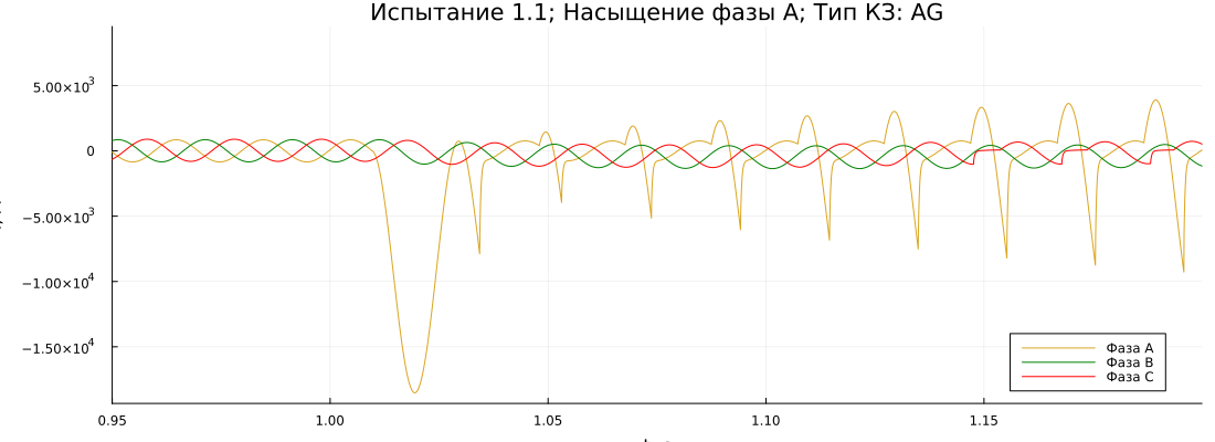
The results obtained can be viewed in the model itself through Visualization or Data Inspector. The simulation results are also recorded in COMTRADE format and stored in a catalog that corresponds to the test parameters.
gr()
plot(
    results["I_TT"].time,
    reduce(hcat, results["I_TT"].value)',
    label = ["Phase A" "Phase B" "Phase C"],
    xlabel = "t, c",
    ylabel = "I, And",
    title = "Test 1.1; Saturation of phase A; Short circuit type: AG",
    color = ["goldenrod" "green" "red"],
    size  = (1100, 400),
    xlimits = (0.95, 1.2),
    legend = :bottomright
)
Test 1.2
Developing short-term conditions. The second short circuit appears with a delay of 10 ms at the point K_delayed.
Since the second short circuit appears half a period after the first, the values of the residual magnetization for the phases of the second point of damage require mirroring (since the residual magnetization must be of the opposite sign of the aperiodic component).
# We save the simulation results in the appropriate catalog.
results_path = "COMTRADE/Test 1.2/Saturation of phase B"
mkpath(results_path)
results_path = results_path * "/BG + CAG"

ScenarioModule.set_delay!(scenario, 10);
# Short circuit at two points
ScenarioModule.set_fault_type!(scenario, "K2_4", "BG", "K_delayed", "CAG");
ScenarioModule.set_controlled_phase!(scenario, 6675, 0.157, phase='B');
# Mirroring the intact phases
scenario.V_strt = [-scenario.V_strt[1], scenario.V_strt[2], -scenario.V_strt[3]];
# Saving the script
save_mode!(scenario)
engee.run(model); # Running the simulation
Test 1.3
Asymmetrical short circuits. Both short circuits occur simultaneously.
Let's conduct an experiment with a short circuit through a transient resistance. To do this, we additionally transfer the value of the transient resistance (in accordance with the standard - 2 ohms) to the second short-circuit point.
# We save the simulation results in the appropriate catalog.
results_path = "COMTRADE/Test 1.3/Phase C saturation"
mkpath(results_path)
results_path = results_path * "/CG + ABG"

# Resetting delays
ScenarioModule.set_delay!(scenario, 0);
# Short circuit at two points
ScenarioModule.set_fault_type!(scenario, "K2_4", "CG", "K_delayed", "ABG");
ScenarioModule.set_controlled_phase!(scenario, 9875, 0.292, phase='C');
# Saving the script
save_mode!(scenario)
engee.set_param!(scenario.path * "/K_delayed",
                "R_pn" => Dict("unit" => "Ohm", "value" => 2),
                "R_ng" => Dict("unit" => "Ohm", "value" => 2))
engee.run(model); # Running the simulation
After the test, we will return the initial values of the transient resistances.:
engee.set_param!(scenario.path * "/K_delayed",
                "R_pn" => Dict("unit" => "Ohm", "value" => 1e-3),
                "R_ng" => Dict("unit" => "Ohm", "value" => 1e-3))
Test 2
In test 2, the location of the short circuit is the point - K3.2. The experiments are similar to test 1.1. It is expected that DZ will be triggered and the phases will be determined correctly.
# Point K3.2
k_line = 0.85 * 0.9;

# We save the simulation results in the appropriate catalog.
results_path = "COMTRADE/Test 2/Phase A saturation"
mkpath(results_path)
results_path = results_path * "/CAG"

# Setting the short circuit type at point K2_4
ScenarioModule.set_fault_type!(scenario, "K2_4", "CAG");
# Setting the controlled phase (saturation phase)
ScenarioModule.set_controlled_phase!(scenario, 7559, 0.147, phase='A');
# Saving the received script
save_mode!(scenario)
engee.run(model); # Running the simulation
Trials 3
In test 3, the operation of TNNP is checked. The set of experiments is similar to test 2. The KZ point is K3.1, the location of which is determined by the results of the TNN setting.
Trials 4
The test 4 The KZ location is the KZ point - K4. It is expected that the first stage DZ will not be triggered, and TU DZ will be triggered.
Test 4.1
The experiments are similar to Test 1.1.
# Point K4
k_line = 0.85 * 1.1;

# We save the simulation results in the appropriate catalog.
results_path = "COMTRADE/Test 4.1/Phase C saturation"
mkpath(results_path)
results_path = results_path * "/CA"

# Setting the short circuit type at point K2_4
ScenarioModule.set_fault_type!(scenario, "K2_4", "CA");
# Setting the controlled phase (saturation phase)
ScenarioModule.set_controlled_phase!(scenario, 6921, 0.136, phase='C');
# Saving the received script
save_mode!(scenario)
engee.run(model); # Running the simulation
Test 4.2
DCZ + OCZ, saturation in one of the phases of DCZ.
# We save the simulation results in the appropriate catalog.
results_path = "COMTRADE/Test 4.2/Saturation of phase B"
mkpath(results_path)
results_path = results_path * "/BC + AG"

# Setting the short circuit type at point K2_4
ScenarioModule.set_fault_type!(scenario, "K2_4", "BC", "K_delayed", "AG");
# Setting the controlled phase (saturation phase)
ScenarioModule.set_controlled_phase!(scenario, 6921, 0.136, phase='B');
# Saving the received script
save_mode!(scenario)
engee.run(model); # Running the simulation
Trials 5
In test 5, the location of the short circuit is the point - K1. It is expected that there will be no protection operation and that the reverse logic of TU DZ and TU TNZNP will be triggered.
The test is carried out in a separate model, in which there are two short circuit units at point K1.
The short circuit is switched off by switch Q1 after 100 ms. The Q1 Switch constant block has a value of 1.0 for switching the Switcher switch to an internal shutdown signal.
Open the model:
engee.open("test_5.engee"); # Opening the model
scenario.path = engee.gcs().path; # In the script, we update the model name
Tests 5.1
The experiments are similar to test 1.1. 100 ms after the moment of the short circuit, Q1 is triggered.
# We save the simulation results in the appropriate catalog.
results_path = "COMTRADE/5.1 Test/Phase A saturation"
mkpath(results_path)
results_path = results_path * "/ABC"

# Setting the short circuit type at point K1
ScenarioModule.set_fault_type!(scenario, "K1", "ABC");
# Setting the controlled phase (saturation phase)
ScenarioModule.set_controlled_phase!(scenario, 10000, 0.118, phase='A');
# Short circuit behind the back (reverse power), therefore, the values of the residual
# The magnetization must be mirrored.
# The phase in which saturation is modeled remains the same
scenario.V_strt = [scenario.V_strt[1], -scenario.V_strt[2], -scenario.V_strt[3]];
# Saving the received script
save_mode!(scenario)
engee.run("test_5"); # Running the simulation
Trials 5.2
Unbalanced short circuits at the same time. 100 ms after the moment of the short circuit, Q1 is triggered.
OKZ + DCZ to the ground through a transient resistance with saturation in the OKZ phase.
DKZ + OKZ with the same damage as in one of the phases of the DKZ with saturation of this phase.
# We save the simulation results in the appropriate catalog.
results_path = "COMTRADE/Test 5.2/Phase A saturation"
mkpath(results_path)
results_path = results_path * "/AB + AG"

# Short circuit at two points
ScenarioModule.set_fault_type!(scenario, "K1", "AB", "K1_add", "AG");
ScenarioModule.set_controlled_phase!(scenario, 9113, 0.109, phase='A');
# Short circuit behind the back (reverse power), therefore, the values of the residual
# The magnetization must be mirrored.
# The phase in which saturation is modeled remains the same
scenario.V_strt = [scenario.V_strt[1], -scenario.V_strt[2], -scenario.V_strt[3]];
# Saving the script
save_mode!(scenario)
# The access control at the additional point will be saved separately
engee.set_param!(scenario.path * "/K1_add", "type" => scenario.K1_add)
engee.run("test_5"); # Running the simulation
After the test, we switch to the main model.
engee.open(model_name); # Switching to the main model
scenario.path = engee.gcs().path; # In the script, we update the model name
Trials 6
Test 6 involves two short-range points - K1 and K2. The external short circuit passes into the internal one. Protection activation is expected in less than 60 ms and correct detection of damaged phases.
When switching the short circuit from K1 to K2, the short circuit in K1 is disabled. To do this, the Switcher Start KZ is switched to transmit the Start_KZ_add signal, which disables the short circuit after a set time delay.
engee.set_param!(scenario.path * "/KZ Switch", "Value" => 0.0)
Test 6.1
The transition of the OKZ from the external to the internal.
# We save the simulation results in the appropriate catalog.
results_path = "COMTRADE/Test 6.1/Saturation of phase B"
mkpath(results_path)
results_path = results_path * "/BG"

ScenarioModule.set_delay!(scenario, 100);
# Short circuit at two points
ScenarioModule.set_fault_type!(scenario, "K1", "BG", "K_delayed", "BG");
ScenarioModule.set_controlled_phase!(scenario, 6675, 0.087, phase='B');
# Saving the script
save_mode!(scenario)
engee.run(model); # Running the simulation
Test 6.2
The transition of the OKZ from the external to the internal with a short circuit in another phase.
The first short circuit (external) occurs in a different phase than the phase of the internal short circuit. Saturation is modeled for the internal short circuit phase. Therefore, the zero transition is monitored for the phase of the external short circuit, and the residual magnetization is assumed as for the internal short circuit, adjusted for the sign of the aperiodic component.
For the internal short circuit in phase C, the sign of the residual magnetization of phase B (external short circuit) is reversed.
Note
For test 6.2 and subsequent tests, the subsystem Saturation time detection is not functional.
# We save the simulation results in the appropriate catalog.
results_path = "COMTRADE/Test 6.2/Phase C saturation"
mkpath(results_path)
results_path = results_path * "/BG + CG"

ScenarioModule.set_delay!(scenario, 35);
# Short circuit at two points
ScenarioModule.set_fault_type!(scenario, "K1", "BG", "K_delayed", "CG");
ScenarioModule.set_controlled_phase!(scenario, 6675, 0.087, phase='C');
# The control phase of the passage of U through zero is the damaged phase of the external short circuit
scenario.controlled_phase = 2;
scenario.V_strt = [scenario.V_strt[1], -scenario.V_strt[2], scenario.V_strt[3]];
# Saving the script
save_mode!(scenario)
engee.run(model); # Running the simulation
Reverse editing of parameters after the test:
engee.set_param!(scenario.path * "/KZ Switch", "Value" => 1.0)
Trials 7
In test 7, two short-range points are involved - K1 and K2. Internal short circuit on the background of the external one. Protection activation is expected in less than 60 ms and correct detection of damaged phases.
A short circuit in K2 occurs after a delay after K1.
The first short circuit (external) occurs in a different phase than the phase of the internal short circuit. Saturation is modeled for the internal short circuit phase. Therefore, the zero transition is monitored for the phase of the external short circuit, and the residual magnetization is assumed as for the internal short circuit, adjusted for the sign of the aperiodic component.
# We save the simulation results in the appropriate catalog.
results_path = "COMTRADE/Test 7/Saturation of phase B"
mkpath(results_path)
results_path = results_path * "/AG + BG"

ScenarioModule.set_delay!(scenario, 105);
# Short circuit at two points
ScenarioModule.set_fault_type!(scenario, "K1", "AG", "K_delayed", "BG");
ScenarioModule.set_controlled_phase!(scenario, 6675, 0.087, phase='B');
# The control phase of the passage of U through zero is the damaged phase of the external short circuit
scenario.controlled_phase = 1;
scenario.V_strt = [-scenario.V_strt[1], scenario.V_strt[2], -scenario.V_strt[3]];
# Saving the script
save_mode!(scenario)
engee.run(model); # Running the simulation
Trials 8
In Test 8 the short circuit point is K1. External short circuit with TT saturation in the intact phase. Defenses are expected to fail.
For the test, you need to make the following changes to the model:
-
Change the position of the Switcher to turn off after a shutter speed of 100 ms
-
Turn on the resistance in the TT zero wire
-
Set the angle of phase A to zero degrees in S1
engee.set_param!(scenario.path * "/Q1 Switch", "Value" => 1.0)
engee.set_param!(scenario.path * "/CT", "use_R0" => true)
engee.set_param!(scenario.path * "/S1", "shift" => Dict("unit" => "deg", "value" => 0.0))
# We save the simulation results in the appropriate catalog.
results_path = "COMTRADE/Test 8/Phase A saturation"
mkpath(results_path)
results_path = results_path * "/BCG"

ScenarioModule.set_delay!(scenario, 0);
# Setting the short circuit type at point K1
ScenarioModule.set_fault_type!(scenario, "K1", "BCG");
# Setting the controlled phase (saturation phase)
ScenarioModule.set_controlled_phase!(scenario, 8923, 0.108, phase='A', Kr=0.86);
# Saving the script
save_mode!(scenario)
engee.run(model); # Running the simulation
Reverse editing of parameters after the test:
engee.set_param!(scenario.path * "/Q1 Switch", "Value" => 0.0)
engee.set_param!(scenario.path * "/CT", "use_R0" => false)
engee.set_param!(scenario.path * "/S1", "shift" => Dict("unit" => "deg", "value" => 6.86))
Conclusion
In the example, the course of testing the relay protection device for compliance with the requirements of GOST-70358 in the model from Appendix A4 was considered.2.
You can additionally automate the test program for variations in saturated phases, short circuit types, current multiplicities, and aperiodic components. To simulate saturation, you will first need to collect data to recalculate the Volt-ampere characteristic of the TT.
Next, assemble all the tests into one script, which loops through the model parameters within the tests and runs the RHYTHM simulation through software control.
The standard requires recording test results in the COMTRADE format, and the model also provides tools for recording simulation results.