Simulation of a thyristor self-excitation system of a synchronous generator
In this example, a model of a synchronous turbo generator TGV-300-2U3 is considered, the excitation winding of which is powered by a controlled thyristor rectifier. The rectifier is connected to the terminals of the generator via a transformer. This arrangement corresponds to the thyristor self-excitation system of a synchronous generator (CTC), related to dependent excitation systems.
Theoretical aspects
In previous примере devoted to a brushless excitation system, the role of powering the excitation winding of a synchronous generator was briefly considered.
In this example, a turbogenerator with a higher capacity of 300 MW is considered. The rotating rotor winding is powered by a thyristor rectifier through contact rings and brushes. The rectifier converts the AC voltage taken from the generator terminals into the DC voltage needed to power the rotor. The use of thyristors allows you to control the amount of rectified voltage, which means that you can regulate the excitation current of the rotor.
The operating voltage of the rotor winding is significantly lower than the voltage at the terminals of the generator. A rectifier transformer is used to adjust the voltage levels. In order to boost the excitation, the transformer is usually designed so that the voltage of its secondary winding exceeds the rated voltage of the rotor.
In case of short circuits in the power system, especially those that are electrically close to the short-circuit site, there is a significant decrease in voltage. To ensure stable operation of the generators at such moments, it is necessary to boost the excitation, ensuring maximum possible maintenance **voltage ** at the terminals of the machine. This is achieved by forcing the excitation, at which the rotor current briefly exceeds the nominal value (approximately 2 times) [1].
The structure of the thyristor excitation system in the model
The excitation boost in the CTC can be implemented in several ways:
-
using a separate group of thyristors;
-
using the same group of thyristors, but powered by a transformer winding with increased voltage;
-
when operating from desoldering the transformer in normal mode and switching to full voltage during boost.
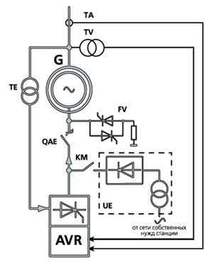
In this model, the rectifier transformer (TE) is designed as a three-winding:
-
winding 2 is operational;
-
winding 3 — boost.
Since the excitation boost mode is not modeled in the example, the boost winding is not used.
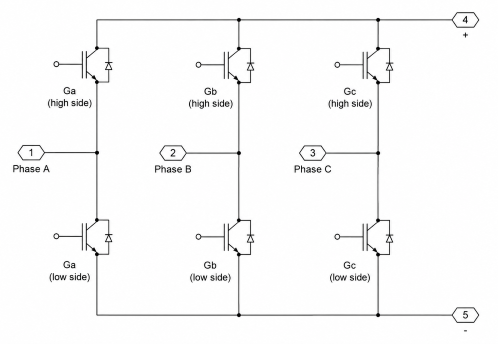
The thyristor rectifier is implemented on the basis of the Converter (Three-Phase) unit operating **in **AC/DC conversion mode. Thyristors are selected as power switches. The location of the thyristors must be taken into account when connecting the converter to the rotor winding. The scheme of the Converter (Three-Phase), made on thyristors, looks like this:
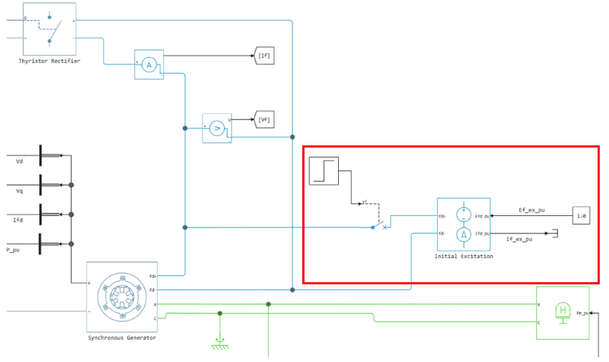
The initial frequency of the system is set to 50 Hz, so the generator (G) is already running at the start of the simulation.
If it is required to simulate the start-up of a generator with an STS, it is necessary to briefly supply power to the rotor winding from an external source (UE). In this case, the Field Circuit block must be added to the excitation circuit.
Automatic field attenuation (QAE) and spark gap (FV) are not implemented in this model.
The ARV-SD*(High-Gain AVR) unit is used as an automatic excitation regulator (AVR).* ARV-SD is most typical for STS[2].
Description of the model
The parameters of the synchronous generator are accepted in accordance with [3]. The missing parameters are determined by the method described in our recent материале. The nominal voltage values of the excitation system are also taken from [3].
According to the simulation scenario, the model is close to the example with a brushless excitation system. During the simulation, a load is applied to the generator. The turbine speed controller restores the frequency to the nominal value, and the ARV provides voltage regulation during the transient process.
Note
After the load is applied, the voltage at the terminals of the generator is not set exactly at the set level. This is due to the lack of an integral component in the ARV-SD regulator.
The integral component ensures the elimination of the steady-state regulation error and corrects the voltage deviation in steady-state mode. There is no such drawback in the ARV-M regulator, since there is an integral link in its structure.
At the initial calculation steps, when searching for steady-state initial conditions, emissions of electrical quantities are observed. To increase the stability of the calculation, the ARV input signals are limited by the Value Limits block. The ARV output signal is in the form of the excitation voltage in relative units, which is further converted into the opening angle of the thyristors (alpha).
The generation of thyristor control pulses is implemented in the Six-Pulse Generator subsystem.
Note
When applying the current voltage angle It is necessary to take into account possible phase shifts due to the connection scheme of the transformer windings. The following rule can be used as a guideline:
the pulse to open the thyristor A+ (Ga low side) must be generated at the time of the line voltage transition through zero from the positive region to the negative, which is equivalent to the phase .
List of literary sources
[1] Korotkov V.F. Automatic regulation in electric power systems: a textbook for universities / V.F. Korotkov. Moscow: Publishing House of the MEI, 2013. 416 p.: ill.
[2] Weinstein R.A. Automatic control of electric power systems in normal and emergency modes: a textbook. Part 1 / R.A. Weinstein, V.V. Shestakova, I.M. Katz; Tomsk Polytechnic University. Tomsk: Publishing House of Tomsk Polytechnic University, 2013. 111 p.
[3] Neklepaev B. N., Kryuchkov I. P. The electrical part of stations and substations: Reference materials for course and diploma design. Moscow: Energoatomizdat, 1989.
[4] Weinstein R. A., Ponamarev E. A., Naumov V. A. & Razumov R. V. (2022). Fundamentals of emergency automation in electric power systems. Tomsk: Publishing House of RIC SRZAU.
Conclusion
In the presented example, a thyristor self-excitation system of a synchronous generator TGV-300-2U3 is simulated. The excitation winding of the generator is powered by a controlled thyristor rectifier, for which the model implements control logic with the generation of power key opening pulses.
This level of detail of the model makes it possible to study in more detail the dynamics of the excitation system and the behavior of its individual elements in transient modes. For in-depth work with the model, you can independently:
-
add logic to boost arousal;
-
simulate the operation of a generator on a power system with a subsequent short circuit;
-
implement our own thyristor rectifier model for detailed analysis of switching processes.