Simulation of a brushless synchronous generator excitation system
In this example, we consider the model ** of a synchronous turbo generator** T-6-2U3, the excitation winding of which is powered by an auxiliary synchronous generator — exciter. The main generator and the exciter are mounted on the same turbine shaft. This arrangement corresponds to a brushless excitation system of a synchronous generator.
Theoretical aspects
A synchronous machine converts mechanical energy into electrical through electromagnetic interaction. The magnetic field created by the rotor, when it rotates, induces an electromotive force in the stator windings, which leads to an electric current in the external circuit.
The following methods are used to generate the magnetic field of the rotor in synchronous machines:
-
Permanent magnets (usually in low-power machines);
-
the excitation winding, powered by direct current.
In this example, a turbogenerator with a capacity of 6 MW is used. Machines of this class in the electric power industry are characterized by the creation of a magnetic flux of the rotor due to direct current flowing through the excitation winding.
Since the rotor is a rotating part of the machine, the task arises of supplying direct current to its winding. There are several solutions to this problem, one of which is a brushless excitation system. This is the system used in the T-6-2U3 turbogenerator.
The structure of the brushless excitation system
The principle of operation of the brushless excitation system is to use an exciter mounted on the same shaft as the main generator. The exciter generates an alternating current, which, after rectification, is applied directly to the excitation winding of the rotor of the main generator. Since the exciter rotates with the generator, there is no need to use brushes and contact rings, which are often used in some types of excitation systems.
The figure below shows typical circuits of a brushless excitation system.:
-
a) a system with an exciter;
-
b) a system without an exciter, powered by the exciter excitation winding from the mains.
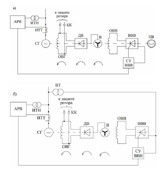
A magnetic field is also required for the exciter to operate. The excitation winding of the exciter can be powered:
- from a separate source (for example, a permanent magnet generator);
- from the electrical network through a transformer and a rectifier device.
In the considered model , the excitation of the exciter is implemented in a simplified form: voltage is applied to the winding of its rotor from an ideal DC voltage source implemented inside the Exciter Field unit. This approach allows us to focus on the study of the operation of the main excitation system without detailing the power supply scheme of the exciter.
Description of the model
The parameters of the main synchronous generator are accepted in accordance with [1]. The missing parameters have been restored using the methodology described in our recent материале.
The nominal values of the voltage and power of the exciter are also taken from [1]. The remaining exciter parameters were selected based on typical values typical for synchronous generators of this power class and voltage level.
The main generator and exciter are implemented using different models of a synchronous machine. For a detailed simulation of the excitation system, a model of the main generator is used with precise consideration of the rotor response — Synchronous Machine Round Rotor. To simulate the exciter, the Synchronous Machine SalientPole* model is used, the functionality of which is sufficient to analyze the operation of the excitation circuit.
Note
The exciter in the brushless excitation system is a reversed synchronous generator in which the rotor is stationary and performs the function of an anchor. This feature does not affect the applicability of the Park–Gorev equations used in the mathematical description of the synchronous generator unit, since these equations take into account the relative rotation between the magnetic field and the machine windings.
The image below shows a synchronous generator with an exciter in spatial form. It also shows the correspondence of its structural elements to the blocks of the model used.
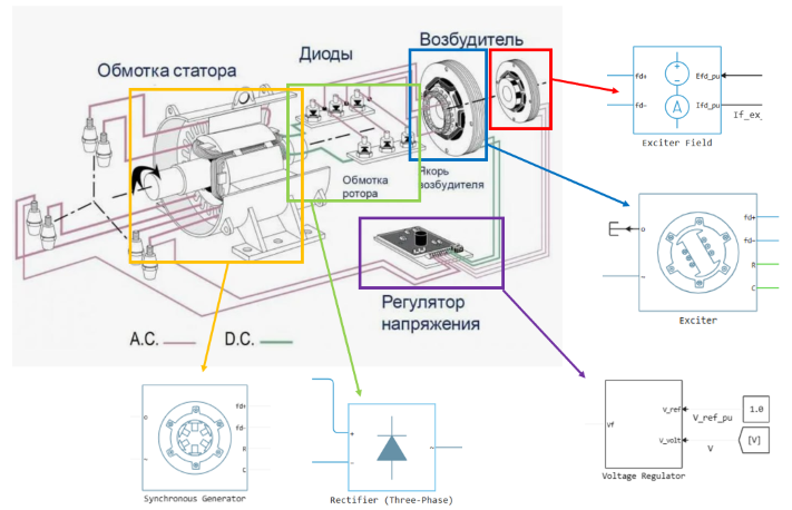
A load is connected to the exciter, simulating various losses in the excitation circuit, including losses on exciter excitations, damping resistances and auxiliary elements.
The model implements ** a scenario of a sudden surge in power** to the generator. With an abrupt increase in load, the rotor speed decreases, as well as the voltage drop at the generator terminals.
Speed and excitation regulators compensate for the deviations that have occurred and return the parameters to the set values. To simplify the model, a PI speed controller and a PID excitation controller are used.
Note
In real electric power systems, more complex automatic control structures are used that take into account several operating parameters and ensure stable synchronous operation of a group of generators.
In the library, in the sections Physical modeling -> Electricity -> Control -> Synchronous machines / turbines and regulators you can find ready-made models of such regulators.
Run the simulation. You can view the results in the Signal visualization section or in the Data Inspector.
List of literary sources
[1] Neklepaev B.N., Kryuchkov I.P. The electrical part of stations and substations: Reference materials for course and diploma design. Moscow: Energoatomizdat, 1989.
Conclusion
In the presented example, a brushless excitation system of a synchronous generator T-6-2U3 is modeled. The exciter is implemented as a separate synchronous machine mounted on the same shaft with the main generator. This approach makes it possible to describe the internal electromagnetic processes in more detail, analyze the transient modes in the excitation circuit, and more accurately take into account the dynamics and delays in the automatic control circuits.
The model uses the reference parameters of the main generator, and for the exciter — typical values typical for machines of similar power. If necessary, the accuracy of calculations can be improved by applying the passport data of the equipment and adapting the model to specific operating conditions and research tasks.