Recording events in the power system in a COMTRADE file
Description of the model
The purpose of this example is to demonstrate the possibility of recording measurements of analog and discrete signals from a model into COMTRADE format files according to the standard IEC 60255-24 using the block To COMTRADE. COMTRADE is a generally accepted format for recording transient waveforms in power systems. Such files can be used in programs for viewing and analyzing events, as well as for playback at test facilities of the [RETOME] type (https://dynamics.com.ru/production/kompleks-51-61 ).
To generate the signals, a model is used containing two 220 kV sources with a dead-earth neutral connected by a two-circuit overhead line (overhead line). At time 1 s of operation of the model, a single-phase short circuit (short circuit) occurs on one of the overhead line circuits on the side of PS B. The short circuit is switched off on the side of PS B by a switch after 0.1 s. From the side of the control panel, the operation of maximum current protection (MTZ) is simplified.
The model's appearance:
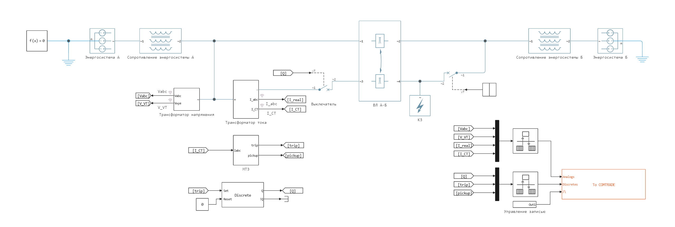
Sources are modeled by a block Voltage Source (Three-Phase). The resistances of the direct and zero sequence of power systems are modeled by the block Coupled Lines (Three-Phase). A short circuit is modeled by a block Fault (Three-Phase). Overhead line is modeled by the [Double-Circuit Transmission] block Line](https://engee.com/helpcenter/stable/en/fmod-electricity-lines/double-circuit-transmission-line.html).
Power system parameters:
| Element | Parameter |
|---|---|
| System A | Equivalent EMF |
| System B | Equivalent EMF |
| Line A-B | |
Voltage and current transformers have conversion coefficients of 220 kV/100 V and 1000 A/1 A, respectively.
Settings for recording analog channels in the COMTRADE format:
| Parameters | Vabc | V_VT | Iabc | I_CT | ||||||||||
|---|---|---|---|---|---|---|---|---|---|---|---|---|---|---|
| Channel Names | Va | Vb | Vc | Va_VT | Vb_VT | Vc_VT | Ia | Ib | Ic | Ia_CT | Ib_CT | Ic_CT | ||
| Channel Phase identifiers | A | B | C | A | B | C | A | B | C | A | B | C | ||
| Channel measurement units | V | V | V | V | V | V | V | A | A | A | A | A | A | A |
| Primary nominal values | 1 | 1 | 1 | 220000 | 220000 | 220000 | 1 | 1 | 1 | 1000 | 1000 | 1000 | ||
| Secondary nominal values | 1 | 1 | 1 | 100 | 100 | 1 | 1 | 1 | 1 | 1 | 1 | |||
| Data scaling identifier | P | P | P | P | S | S | S | P | P | P | S | S | S | |
Discrete channels record the switch position signals from the side of the control panel A "Q", the start of the "pickup" and the operation of the "trip" protection.
Simulation results
The results can be viewed in Engee in the signal visualization module. For example, a current transformer is modeled taking saturation into account, its graphs of the primary and reduced secondary current of phase A are shown below:
.png)
By applying a control signal to the control input of the To COMTRADE unit, waveforms were recorded 0.5 seconds before and after the moment of the short circuit. After the simulation is completed, the measurements.cfg and measurements.dat files will appear in the current folder. The user can change the file names and paths to save in the To COMTRADE block settings.
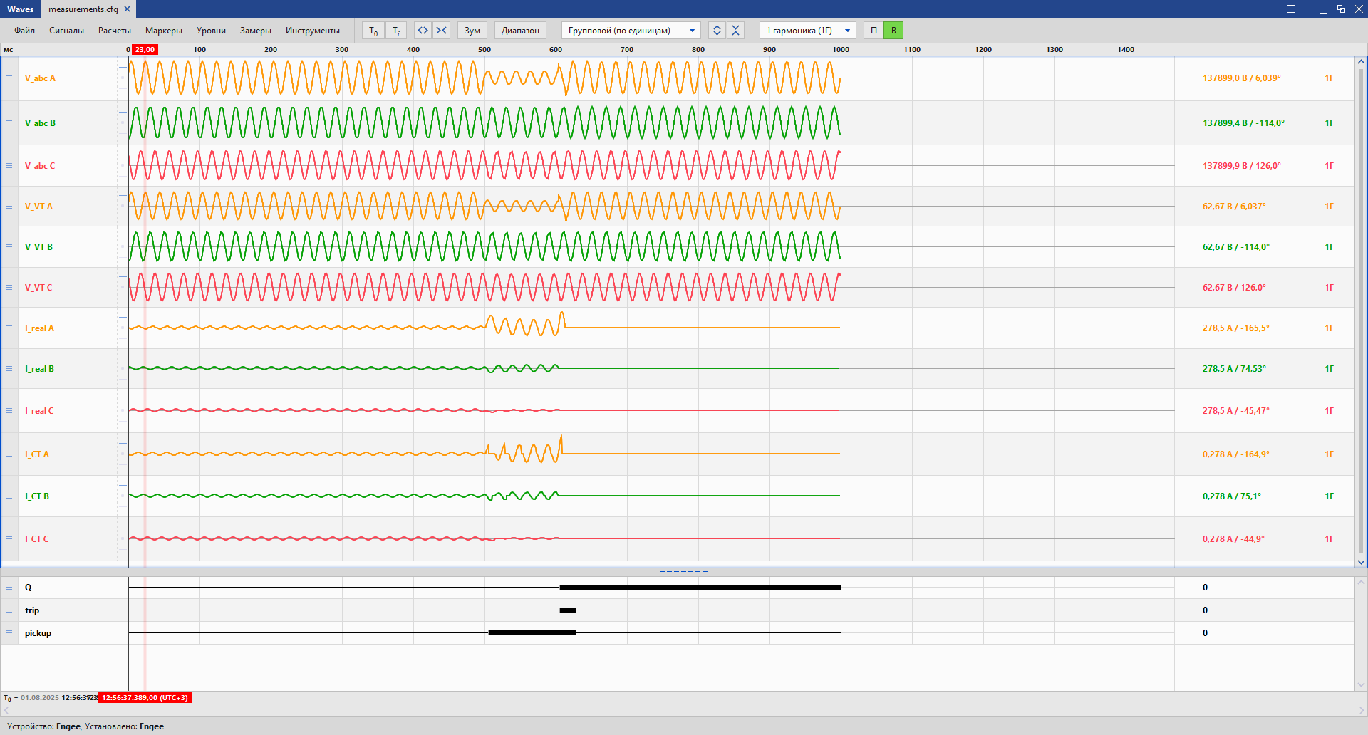
To check the recorded COMTRADE files, they were opened in a special viewing program. In this example, the [Waves] program was selected(https://dev.ekra.ru/software/package?packageId=2 ) from the company NPP EKRA LLC. Screenshot of recorded waveforms from the program:
Conclusions
In this example, the operation of the To COMTRADE unit for recording measurements of analog and discrete signals from a power system model was demonstrated.The recorded files were checked using the Waves viewer.