Computer-aided design of CIC decimators: from behavioral model to Verilog code
Efficient and resource-efficient filter architectures occupy a special place in modern digital signal processing, among which CIC (Cascaded Integrator-Comb) filters stand out due to their unique ability to perform decimation and interpolation without using multipliers. This article presents a comprehensive approach to the design of CIC decimators with automated generation of the filter structure and intelligent control of valid signals, culminating in the generation of hardware-oriented Verilog code.
In our example, the CIC decimator design methodology is divided into three consecutive stages, forming a complete cycle from concept to hardware implementation.:
1. Automatic generation of filter structure
The algorithm automatically creates a hierarchical architecture of the CIC filter according to the specified parameters (order, decimation, bit depth). Automation eliminates manual design errors and reduces development time.
2. Intelligent control of valid signals
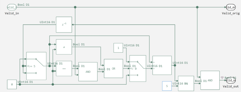
Subsystem Gen_valid generates clock validation signals synchronized with decimation processes. The architecture includes a counter with a decimation coefficient, pulse generation logic, and a filter control mechanism via a signal. Enable.
3. Verilog code generation from the model description
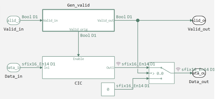
The process of transforming a behavioral model into a hardware description in the Verilog language includes the transformation of mathematical operations into hardware blocks, the generation of registers and I/O interfaces with optimization in terms of speed and resource intensity. The upper level of the model from which we generate code is shown below.
Now let's move on to the implementation, the code below sets the basic parameters of the CIC filter: generates a unique model name, determines the path to save the file, sets the decimation coefficient R=5 and the fixed-point format of 16 bits with 14 fractional digits.
# CIC Filter Parameters
name_model = "cic_$(round(Int, rand() * 10000))"
Path = (@__DIR__) * "/" * name_model * ".engee"
println("Path: $Path")

R = 5  # Decimation coefficient
FIXED_POINT_TYPE = "fixdt(1, 16, 14)"
Next, we will create the basic structure of the CIC filter.
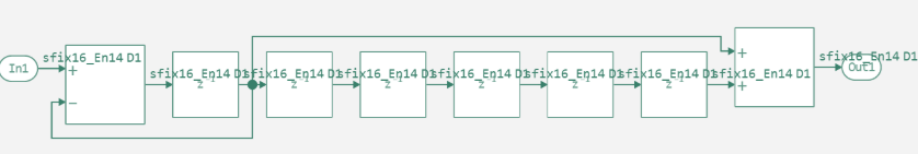
First, a new model is created with an input and output port, and a fixed-point format is set. Then an integrator section is added, consisting of an adder and a delay unit connected in a feedback loop to implement integration. Further, cascades of single delays are created in the cycle, the number of which corresponds to the decimation coefficient R = 5. The combinatorial part is formed by adding an adder that connects the output of the integrator to the output of the last delay to implement differentiation. After forming the complete filter structure, the model is saved to a file and uploaded back for further work.
engee.create(name_model)
engee.add_block("/Basic/Ports & Subsystems/In1", name_model*"/")
engee.add_block("/Basic/Ports & Subsystems/Out1", name_model*"/")
engee.set_param!(name_model*"/In1",
    "OutDataTypeStr" => "Fixed-point",
    "OutDataTypeStrFixed" => FIXED_POINT_TYPE)
engee.add_block("/Basic/Math Operations/Add", name_model*"/Integrator_Add")
engee.add_block("/Basic/Discrete/Unit Delay", name_model*"/Integrator_Delay")
engee.set_param!(name_model*"/Integrator_Add",
    "Inputs" => "+-",
    "OutDataTypeStr" => "Fixed-point",
    "OutDataTypeStrFixed" => FIXED_POINT_TYPE)
engee.add_line("In1/1", "Integrator_Add/1")
engee.add_line("Integrator_Add/1", "Integrator_Delay/1")
engee.add_line("Integrator_Delay/1", "Integrator_Add/2")
prev_delay = "Integrator_Delay"
for i in 1:R
    delay_name = "Delay_$i"
    engee.add_block("/Basic/Discrete/Unit Delay", name_model*"/"*delay_name)
    if i == 1
        engee.add_line("Integrator_Delay/1", delay_name*"/1")
    else
        prev_delay_name = "Delay_$(i-1)"
        engee.add_line(prev_delay_name*"/1", delay_name*"/1")
    end
    prev_delay = delay_name
end
engee.add_block("/Basic/Math Operations/Add", name_model*"/Comb_Add")
engee.set_param!(name_model*"/Comb_Add",
    "OutDataTypeStr" => "Fixed-point",
    "OutDataTypeStrFixed" => FIXED_POINT_TYPE)
engee.add_line("Integrator_Delay/1", "Comb_Add/1")
engee.add_line("Delay_$R/1", "Comb_Add/2")
engee.add_line("Comb_Add/1", "Out1/1")
engee.save(Path)
model = engee.load(Path, force=true)
The function below launches the CIC filter model, it checks whether the model is loaded, opens or loads it, performs a simulation and returns the results, then we extract the simulation results:
Valid_out- validation signal (active every 5 clock cycles)Data_out- output data (valid samples only)Data_CIC- all filter data
And we build two graphs:
- Comparison
Data_outandData_CIC- shows the decimation effect - The signal
Valid_out- demonstrates the frequency of validation
function run_model( name_model)
    Path = (@__DIR__) * "/" * name_model * ".engee"
    if name_model in [m.name for m in engee.get_all_models()] # Checking the condition for loading a model into the kernel
        model = engee.open( name_model ) # Open the model
        model_output = engee.run( model, verbose=true ); # Launch the model
    else
        model = engee.load( Path, force=true ) # Upload a model
        model_output = engee.run( model, verbose=true ); # Launch the model
        engee.close( name_model, force=true ); # Close the model
    end
    sleep(0.1)
    return model_output
end
run_model("cic_5") # Launching the model.
Valid_out = collect(simout["cic_5/CIC_decim/Gen_valid/Logical Operator.1"]).value
Data_out = collect(simout["cic_5/CIC_decim/Switch.1"]).value
Data_CIC = collect(simout["cic_5/CIC_decim/CIC.Out1"]).value

p1 = plot(Data_out, label="Data_out", linewidth=2, ylabel="Meaning", title="The output of the CIC filter", legend=:topright)
plot!(p1, Data_CIC, label="Data_CIC",  linewidth=2, linestyle=:dash)
p2 = plot(Valid_out, label="Valid_out", linewidth=2, ylabel="A valid signal", title="Valid signal (valid)", color=:red, legend=:topright)
plot(p1, p2, layout=(@layout [a; b]), size=(800, 600))
The first graph shows zero values between valid counts, which confirms that the decimator is working correctly.
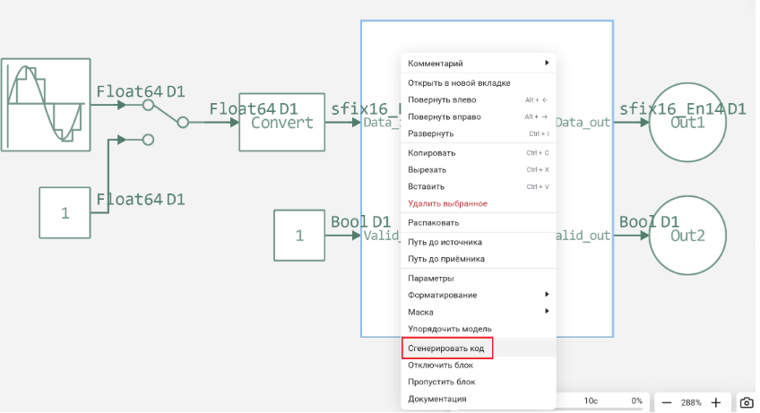
Now let's generate the code.
Based on the results, we see that the correct hardware code of the 5th-order decimator CIC has been generated. The architecture is implemented hierarchically with the main module integrating a CIC filter and a valid signal generator. The system is energy efficient - the filter is activated only with valid data, using a fixed-point format of 16 bits with 14 fractional digits. Implemented a 5:1 decimation with a valid pulse every 5 clock cycles. The structure is optimized - there are no multiplications, only addition and subtraction operations. The code is ready for synthesis in FPGA and fully corresponds to the original model.
To make sure that the filter is working properly, we wrote a simple test.:
module tb_cic;
  reg clock;
  reg reset;
  wire valid_out;
  wire [15:0] data_out;

  reg [15:0] data_in;
  reg valid_in;

  real real_output_value;

  integer results_file;
  integer sim_log;

  integer clock_count = 0;
  integer sample_count = 0;

  cic_5_CIC_decim dut (
    .clock(clock),
    .reset(reset),
    .io_Data_in(data_in),
    .io_Valid_in(valid_in),
    .io_Valid_out(valid_out),
    .io_Data_out(data_out)
  );

  always @(*) begin
    real_output_value = $itor($signed(data_out)) / 16384.0;
  end

  always #5 clock = ~clock;

  always @(posedge clock) begin
    if (!reset) clock_count <= clock_count + 1;
  end

  initial begin
    clock = 0;
    reset = 1;
    data_in = 16'h2000;
    valid_in = 1;

    results_file = $fopen("results.txt", "w");
    sim_log = $fopen("simulation.log", "w");

    $fdisplay(results_file, "Clock\tSample\tValid_out\tData_hex\tData_float");
    $fdisplay(sim_log, "Начало симуляции CIC дециматора");

    #20 reset = 0;
    $fdisplay(sim_log, "\text{Сброс} \text{снят} \text{в} time = %0d", $time);

    #1000;
    $fdisplay(sim_log, "Завершение симуляции. Всего тактов: %0d, Валидных выходов: %0d",
              clock_count, sample_count);
    $fclose(results_file);
    $fclose(sim_log);
    $finish;
  end

  always @(posedge clock) begin
    if (!reset) begin
      if (clock_count == 10) data_in = 16'h4000;
      else if (clock_count == 20) data_in = 16'h6000;
      else if (clock_count == 30) data_in = 16'h2000;
      else if (clock_count == 40) data_in = 16'h0000;
    end
  end

  always @(posedge clock) begin
    if (!reset) begin
      if (valid_out) begin
        sample_count = sample_count + 1;
        $fdisplay(results_file, "%0d\t%0d\t%d\t\t%h\t\t%0.4f",
                  clock_count, sample_count, valid_out, data_out, real_output_value);
        $fdisplay(sim_log, "Valid выход @ такт %0d: data=%h (float=%0.4f)",
                  clock_count, data_out, real_output_value);
      end

      if (clock_count > 10 && valid_out) begin
        if ((clock_count % 5) != 0) begin
          $fdisplay(sim_log, "ОШИБКА: valid_out=1 в такте %0d (должен быть каждый 5-й такт)", clock_count);
        end
      end

      if (sample_count >= 50) begin
        $fdisplay(sim_log, "Достигнуто 50 валидных выходов. Завершение.");
        $fclose(results_file);
        $fclose(sim_log);
        $finish;
      end
    end
  end

  initial begin
    #10;
    forever begin
      @(posedge clock);
      if (!reset) begin
        if ($time > 100 && $time < 200) begin
          $fdisplay(sim_log, "Такт %0d: valid_in=%d, valid_out=%d, data_in=%h",
                    clock_count, valid_in, valid_out, data_in);
        end
      end
    end
  end

endmodule
# Defining the path to the directory with the code
prj_path = joinpath(@__DIR__, "cic_5_CIC_decim_code")
# Checking the existence of the directory
if !isdir(prj_path)
    error("Directory not found: $prj_path")
end
# Temporarily moving to the project directory
cd(prj_path) do
    # Compilation
    run(`iverilog -o sim tb_cic.v cic_5_CIC_decim.v CIC.v Gen_valid.v`)
    # Running the simulation
    run(`vvp sim`)

    # Reading results from a file
    if isfile("results.txt")
        lines = readlines("results.txt")
        out_model = Float64[]
        for line in lines
            if occursin(r"^\d+\t", line)  # We are looking for rows with data (starting with a digit)
                parts = split(line, "\t")
                if length(parts) >= 2
                    push!(out_model, parse(Float64, parts[2]))
                end
            end
        end
        # Output of the table header
        println("No.\T Value")
        println("--\t-------")
        # Output of only the first 8 values
        for i in 1:min(8, length(out_model))
            println("$i\t$(out_model[i])")
        end
        # Show how many records there are in total
        println("\nThe number of entries in the file: $(length(out_model))")
    else
        println("The file results.txt not found!")
    end
end
Testing has confirmed the correct operation of the CIC decimator of the 5th order. The system is functioning normally, as evidenced by the results obtained. The decimation works according to a preset ratio of 5:1 - in 100 simulation cycles, 20 valid output samples were obtained, which corresponds to the expected value. The output data is not zero, which confirms the filter's operability and signal transmission through the entire processing chain.
The correctness of valid signals is confirmed by the frequency of their activation - the valid_out signal is activated every 5th clock cycle, as intended in the decimator architecture. The graph of the output values shows the expected progression from 1.0 to 8.0, which corresponds to the work of the integrator accumulating the input data.
Conclusion
The results obtained confirm that the CIC filter of the 5th order functions correctly, decimation with a coefficient of 5:1 is implemented correctly, the structure of integrators and combinators processes data in accordance with theoretical expectations, and the valid signal generator is working properly.
The system is ready for use in real-world digital signal processing applications, and you can proceed to more complex tests with different types of input signals to fully verify performance.