OPSK receiver and FPGA transmitter
This example demonstrates a test model of a communication system designed for code generation. A number of simplifications have been deliberately introduced into the model in order to clearly show the process of transition from a simple concept to ready-made code for FPGAs. A full description of the project and a detailed analysis of all stages of work are presented in this article.https://habr.com/ru/companies/etmc_exponenta/articles/969564
/>)
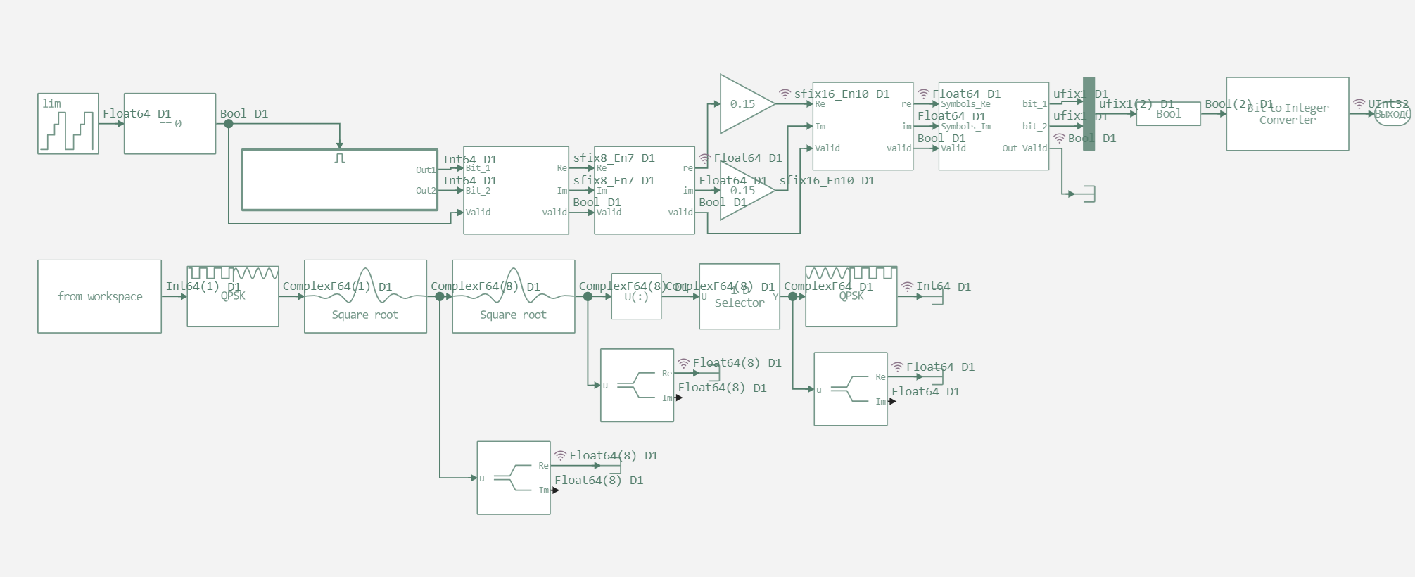
The first model that we will consider compares blocks developed for code cogeneration with blocks from the Engee standard library. This allows us to verify the algorithms we have created.
function run_model( name_model)
    Path = (@__DIR__) * "/" * name_model * ".engee"
    if name_model in [m.name for m in engee.get_all_models()] # Checking the condition for loading a model into the kernel
        model = engee.open( name_model ) # Open the model
        model_output = engee.run( model, verbose=true ); # Launch the model
    else
        model = engee.load( Path, force=true ) # Upload a model
        model_output = engee.run( model, verbose=true ); # Launch the model
        engee.close( name_model, force=true ); # Close the model
    end
    sleep(0.1)
    return model_output
end
run_model("test_sim") # Launching the model.
out_v_data = collect(simout["test_sim/out_v"]).value
out_ref_data = collect(simout["test_sim/out_ref"]).value

p_ref = plot(out_ref_data,
           seriestype = :steppost,  # Graph type - steps
           label="The reference signal",
           linewidth=2,
           color=:orange,
           ylabel="Meaning",
           title="Reference signal (out_ref)",
           xlims=(0, 16),  # Range from 0 to 16
           legend=:topright)

p_v = plot(out_v_data,
           seriestype = :steppost,  # Graph type - steps
           label="The model's signal for code generation",
           linewidth=2,
           color=:blue,
           ylabel="Meaning",
           title="The model's signal for code generation (out_v)",
           xlims=(0, 150),  # Range from 0 to 150
           legend=:topright)
plot(p_ref, p_v,
     layout=(@layout [a; b]),  # Two graphs vertically
     size=(800, 600))
Having plotted the QPSK demodulator outputs for both models, we see their identical operation. The only difference in behavior is that due to the presence of a validity signal in the code generation model, all samples are excluded from its output until the full frame is accumulated. Based
on the test, it can be concluded that the filters and modulators we have developed are working correctly.
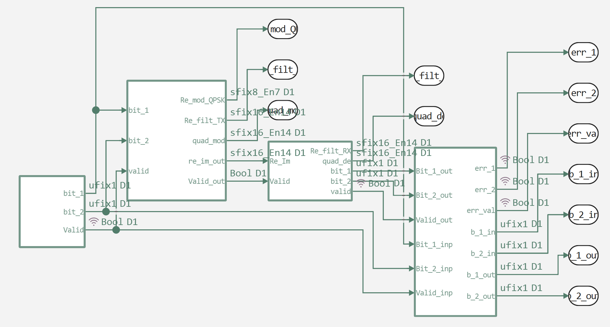
The second model that we will consider is the final model for code generation. It includes a test data generator and error output between input and output, as well as implements frequency offsets, without implementing a low-pass filter, a partial implementation of this algorithm is aimed primarily at demonstrating this feature, rather than fully displaying the functionality..
run_model("model") # Launching the model.
err_bit_1_data = collect(simout["model/System/err_bit_1"]).value
err_bit_2_data = collect(simout["model/System/err_bit_2"]).value
err_val_data = collect(simout["model/System/Test.err_val"]).value
sum_err_bit_1 = sum(err_bit_1_data)
sum_err_bit_2 = sum(err_bit_2_data)
sum_err_val = sum(err_val_data)
println("The sum of errors on the first bit: ", sum_err_bit_1)
println("The sum of errors on the second bit: ", sum_err_bit_2)
println("The sum of errors by validations:    ", sum_err_val)
As we can see, the model does not register errors. This means that, at least without taking into account the communication channel, the system is working correctly.
The next step is to generate the code on Verilog and verify its functionality. In addition to the code itself, we also created a model in C using a verifier for functional verification.
run_model("verification") # Launching the model.
To check the operability of the generated code, by analogy with the previous model, we will calculate errors for bit streams and validity signals.
err_bit_1_data = collect(simout["verification/C Function.1"]).value
err_bit_2_data = collect(simout["verification/C Function.2"]).value
err_val_data = collect(simout["verification/C Function.3"]).value
sum_err_bit_1 = sum(err_bit_1_data)
sum_err_bit_2 = sum(err_bit_2_data)
sum_err_val = sum(err_val_data)
println("The sum of errors on the first bit: ", sum_err_bit_1)
println("The sum of errors on the second bit: ", sum_err_bit_2)
println("The sum of errors by validations:    ", sum_err_val)
As we can see, the generated code works identically to the original model. This gives you confidence that, in the absence of problems with resources or time characteristics (timings), it will function correctly on the FPGA, the file structure of the generated project itself is presented below.
current_dir = @__DIR__
println("File structure in the directory: $current_dir")
println()
for (root, dirs, files) in walkdir(current_dir)
    for dir in dirs
        if startswith(dir, "model_System_code")
            println("$dir/")
            dir_path = joinpath(root, dir)
            for file in readdir(dir_path)
                println("  └── $file")
            end
            println()
        end
    end
end
Conclusion
The results of all testing stages (visual comparison of graphs, counting of bit errors, verification with the C-model) clearly indicate the project's operability. The developed algorithms have been verified, and the process of automatic code generation from the model has been worked out and has given the correct result. Thus, the presented example confirms the viability of the methodology of Model-Based Design for the creation of digital communication systems.
The full path from a functional model in the Engee environment to a ready-to-synthesize code in the hardware description language is shown, which significantly speeds up the FPGA development process.