Verilog Code Generation Capabilities
Introduction
In today's digital world, computing performance and energy efficiency are often determined by the hardware platform. Central processing units (CPUs) are versatile, but not always optimal for specialized tasks such as real-time signal processing, computer vision, communication protocols, or neural networks. Here they come to the fore FPGAs (Programmable Logic Integrated Circuits).
FPGAs are a unique class of microcircuits, the internal structure of which (connections of logical elements, memory blocks, specialized nodes) can be repeatedly reprogrammed by the developer himself after manufacture. This allows you to create not software, but physical hardware, ideally tailored to a specific algorithm. As a result, unprecedented performance is achieved: parallelism, predictable response time, and minimal power consumption.
However, programming an FPGA is fundamentally different from writing code for a processor. Designing on Verilog (RTL-level) requires specific, hardware-based thinking, a deep understanding of time diagrams, timing, and resource optimization. This creates a high entry threshold and increases the development time of complex algorithmic modules. Instead of sequential instructions, it is necessary to describe the hardware here — a digital circuit consisting of registers, adders, multiplexers, and finite automata operating in parallel. For this purpose, there are Hardware Description Languages (HDL — Hardware Description Language). The two main representatives are VHDL and Verilog.
Verilog is the language in which the developer describes how elements should be connected and how they should behave over time. The compiler (synthesizer) converts this description into a configuration (bitstream) for the FPGA, actually "stitching" the circuit you created into it. So you are not writing a program, but designing a digital device.
But the transition from a mathematical algorithm to its description on Verilog is a complex and time—consuming process that requires in-depth knowledge of digital circuitry. This is where high-level synthesis tools such as Engee come to the rescue.
Key structural elements of FPGAs: DSP, FF, LUT and BRAM
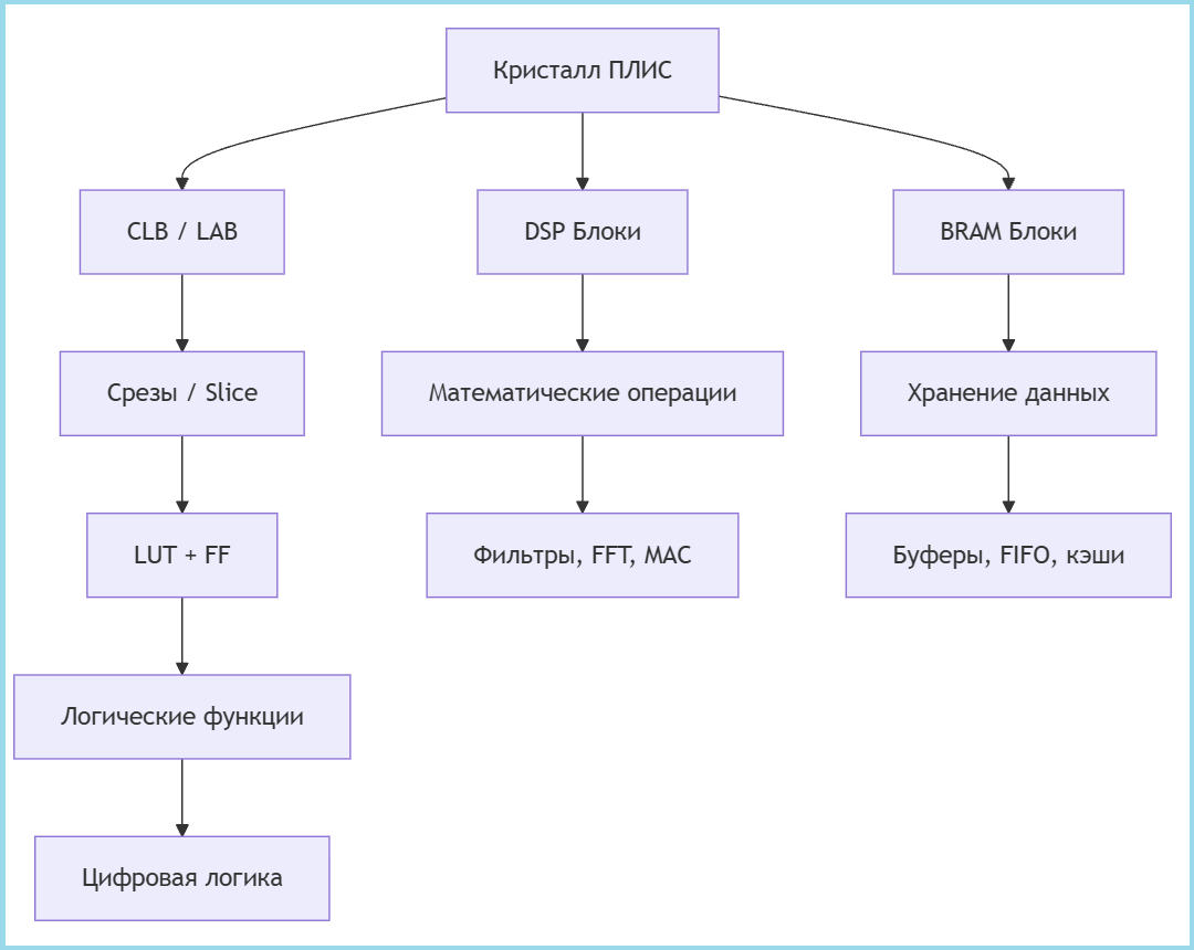
The FPGA architecture is based on configurable logic blocks (CLB, or LAB in Altera/Intel terminology). They are the basic building elements and consist of smaller slice modules. Each slice includes a programmable truth table (LUT) for implementing combinational logic and a trigger (FF) for storing data. It is these elements that perform the basic logic and register functions, forming the core of any digital circuit.
For high-performance computing, specialized DSP blocks are integrated into the FPGA. Their key feature is optimization for multiplication-accumulation (MAC) operations. Such blocks are capable of not only quickly multiplying numbers, but also adding a third value to the result, and then accumulating the amount in the accumulator. They often also include a pre-adder that allows addition to be performed before multiplication, for example, using the formula (A+D)×B+C. This makes them indispensable for digital signal processing, filter implementation, and neural networks.
The built-in block memory (BRAM) provides the FPGA with data storage resources. It is a synchronous dual-port memory that allows you to independently read and write data to two addresses at the same time. BRAM can be configured in various formats and often supports built-in functions such as FIFO controllers for queuing data, as well as error control mechanisms (ECC) to improve the reliability of information storage.
1. LUT (Look-Up Table) — Setup Table
- Programmable truth table
- The main element for the implementation of combinational logic
Functions:
- Any Boolean function
- Small distributed memory
- Can work as a shift register (SRL)
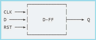
2. FF (Flip-Flop) — Trigger
- D-trigger for storing 1 bit
- Synchronized by a clock signal
Kinds:
- FDCE: Asynchronous Reset (Clear)
- FDPE: With asynchronous installation (Preset)
- FDRE: With synchronous reset
Scheme:
3. DSP (Digital Signal Processor) — DSP Unit
- A specialized block for mathematical operations
- Optimized for multiplication-accumulation
The structure of a typical DSP block:
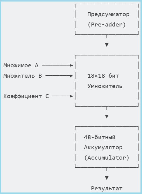
The diagram shows a typical architecture of a DSP unit. It not only performs fast multiplication (A×B), but also has a Pre-adder for calculating (A+D) before multiplication, as well as an accumulator for multiplication-accumulation operations (MAC), which is critical for digital filters and convolutions.
Basic operations:
- P = A × B + C — MAC operation
- P = (A + D) × B + C — with a pre-summator
- Pattern detection — comparison with a sample
4. BRAM (Block RAM) — Block memory
- Built-in RAM
- Dual-port synchronous memory
Features:
- True dual-port — both ports are independent
- Synchronous operation — registers on inputs/outputs
- Built-in FIFO controller — in some models
- ECC support — error control
Key findings:
- LUT — the basis of digital logic, replaces thousands of individual logic gates
- FF — provide synchronicity and state storage
- DSP — accelerate mathematical calculations by 10-100 times
- BRAM — provide fast local memory without external chips
It is the combination of these four elements that allows FPGAs to efficiently implement complex digital systems, from simple controllers to signal processing processes.
How Verilog works using the example of XOR
1. Source code on Verilog
module half_adder(
    input a, b,
    output y
);
    assign y = a ^ b; // XOR операция
endmodule
- The simplest half-accumulator
- Uses the XOR operator (^)
- Calculates the sum without taking into account the transfer
2. Synthesis and optimization
- The Verilog compiler analyzes the code
- Creates an intermediate representation of the schema
- Optimizes logic to minimize delays
Scheme of implementation of XOR through LUT in FPGA
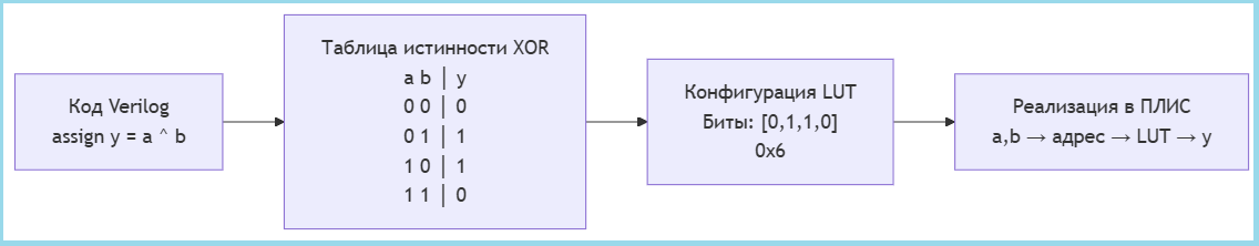
The essence: All XOR logic is packed into 4 LUT configuration bits, which are loaded into the FPGA and work as a lookup table — the inputs become an address, the output a value from the corresponding memory location.
Article review
This article is a practical guide that will guide you through the full cycle of creating a verified hardware module on Verilog from an algorithmic model. We will not only show you how, but also explain in detail why:
- Why do we need a fixed point instead of a floating point? — The answer lies in the efficiency of using FPGA resources.
- How does vector code turn into a pipeline scheme? — This is the basis of high productivity.
- How can I automatically generate readable and optimized Verilog code? — Using templates and system settings.
- How can I be sure that the created scheme is working correctly? — Using two-step verification using Verilator and Icarus Verilog.
As a simple but illustrative example, we'll take a trapezoid parameter calculator. This training example is ideal for demonstrating the entire cycle of model-oriented design: we will see how the idea turns into an algorithm, the algorithm into a fixed—point pipeline model, and the model into a hardware implementation ready for synthesis that has passed strict verification. Using his example, we will clearly show the typical operations (addition, multiplication) that form the basis of real DSP algorithms, revealing the key nuances of the approach.
Auxiliary functions
Let's start by describing the functions of the auxiliary library:
-
run_model(name)— loads and executes the Engee model. -
read_v(filename)— Reads and outputs the contents of the specified file, convenient for debugging. -
extract_verilog_parameters(output)— analyzes the output of the Verilog simulation, extracting numerical parameter values. -
The code at the end of the library checks for the file
tb.vand generates it if the file is missing.
include("helper_lib.jl")
Working with fixed-point numbers in Engee
In hardware design and digital signal processing, fixed-point numbers are used instead of floating-point numbers for several key reasons:
- This approach requires fewer logical elements and memory when implemented in hardware.
- Operations with this type of data are performed in a fixed number of clock cycles
- Simple operations without normalization are performed much faster than similar operations with a floating sign.
In Engee, the function is used to work with a fixed point fi(), which has the following syntax:
x = fi(Value, Sign, Total_bits, Fractional_bits)
Function Parameters:
| Parameter | Description | Example |
|---|---|---|
Value |
The original decimal number | 128.9 |
Sign |
Type of sign: 1 - iconic, 0 - unsigned |
1 |
Total_bits |
Total number of digits (bits) | 16 |
Fractional_bits |
Number of fractional bits | 7 |
A practical example:
Value = 128.9
Sign = 1;
Total_bits = 16;
Fractional_bits = 7;

x = fi(Value, Sign, Total_bits, Fractional_bits)
println("fi: $x")
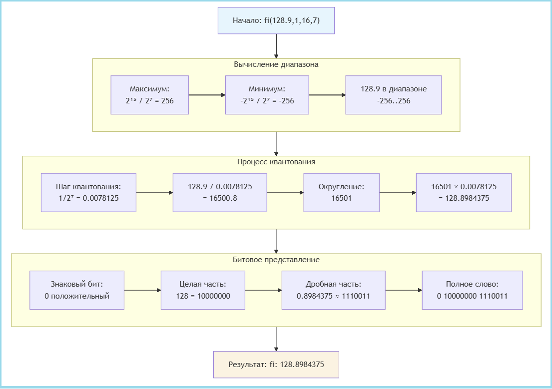
As shown in the figure below, the process of creating a fixed-point number involves three main steps:
-
Calculating the range — determining the minimum and maximum values that the selected format can represent
-
The quantization process is the transformation of the initial number taking into account the quantization step
-
Bit representation — formation of the final binary word
When performing operations with fixed-point numbers in Engee, the bit depth of the result is automatically changed, which is important to take into account in order to optimize resource usage.
display(x + fi(2.8,0,8,6))
display(3x)
As we can see, when adding numbers with different formats, the system automatically increases the bit depth by 1 bit to prevent overflow. A more significant expansion occurs when multiplying by integers of the type Int64 — in this case, 64 bits are added to the whole part, which leads to a significant increase in the bit depth of the result (from 16 to 80 bits).
Automatic expansion of the bit depth, although it prevents overflow errors, often leads to excessive use of resources. To create memory-optimal hardware solutions, it is recommended to use explicit type conversion with bit control, and use fixed-point numbers instead. Int64 for constants and adjust the bit depth of the results manually if necessary.
A system model of an algorithm for calculating trapezoid parameters
To test the algorithm initially, we implemented a Julia system model that calculates the basic geometric parameters of a trapezoid: perimeter (P), midline (m), and area (S) for different height values.
a, b, c, d = 5, 7, 3, 4
h = [4,5]

P = a + b + c + d
m = (a + b) / 2
S = m .* h

println("Perimeter P = $P")
println("The middle line is m = $m")
println("Area S = $S")
This implementation is a vectorized model where the area calculation operation is performed on an array of height values. h = [4, 5] using the operator .*. The model works with floating point data types (Float64), which ensures high accuracy and ease of debugging.
Although this approach allows you to quickly verify the correctness of the algorithm and obtain reference results, it ** does not support hardware code generation**. Vectorized operations and floating-point types cannot be directly converted into efficient hardware implementations, which requires creating a separate fixed-point model and pipelining for subsequent Verilog code generation.
A model for generating Verilog code
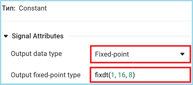
To move to a hardware implementation, you need to create a model that supports code generation. The first step in this process is to define the input arguments using a fixed point.
Unlike the floating-point system model, we set input parameters with a single data type to generate the Verilog code. fixdt(1, 16, 8) — signed 16-bit format with 8 fractional bits, the same data type is used solely for simplification, you can choose the optimal types if necessary.
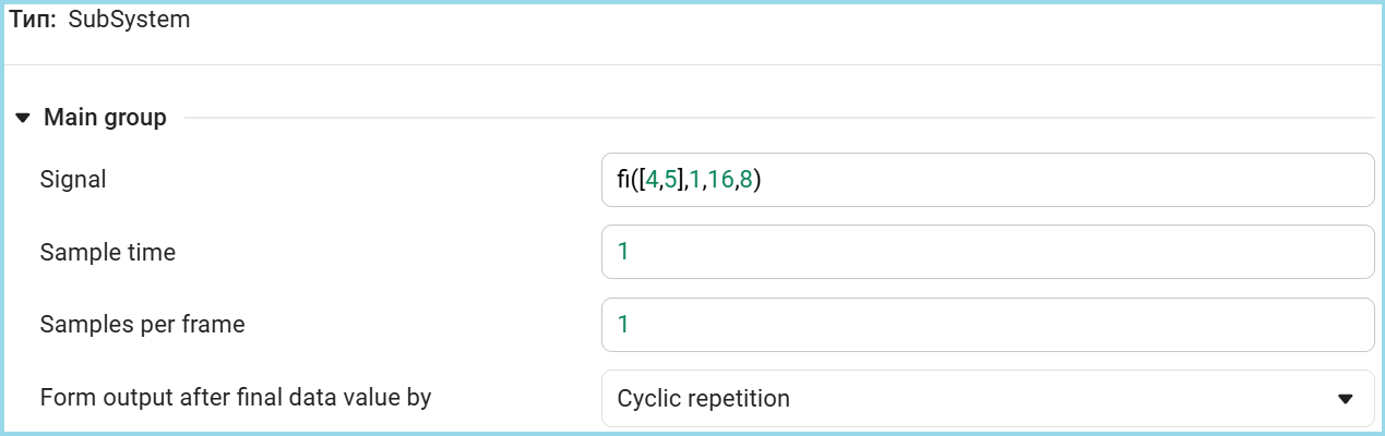
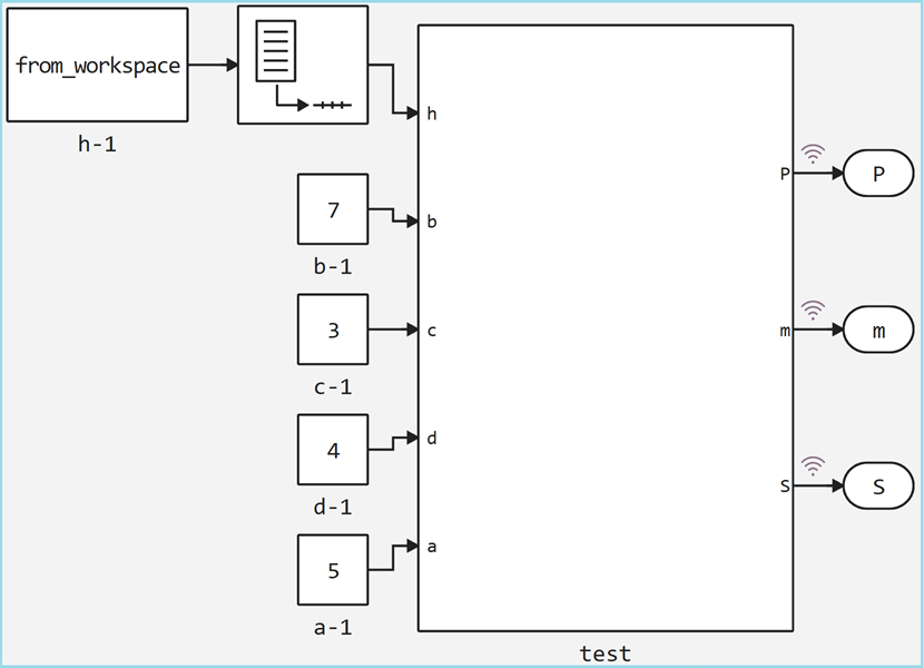
Since in our example the height is h represented by a vector type [4, 5] for the hardware implementation, it is necessary to organize sequential processing of these values. In the Engee model, this is achieved using a pipelined approach, where each value is processed in a separate clock cycle.
For sequential data supply, the Signal From Workspace block is used, which splits the vector of values into separate samples that enter the model at a fixed time interval. In this case, both height values will be processed in two consecutive calculation cycles. The settings of our block are shown below.
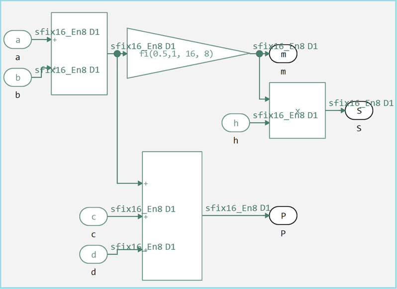
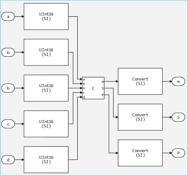
Now let's look at the entire top level of the model, it retains the same calculation logic as the original script, but with a key difference in the data types. Input parameters a, b, c, d match the values from the initial test (5, 7, 3, 4), however, they are now represented in a fixed-point format. fixdt(1, 16, 8).
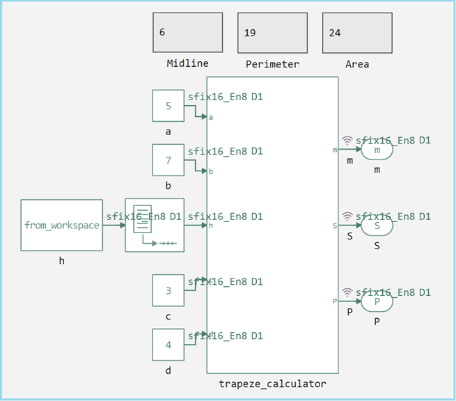
The following settings were also enabled to debug the model.
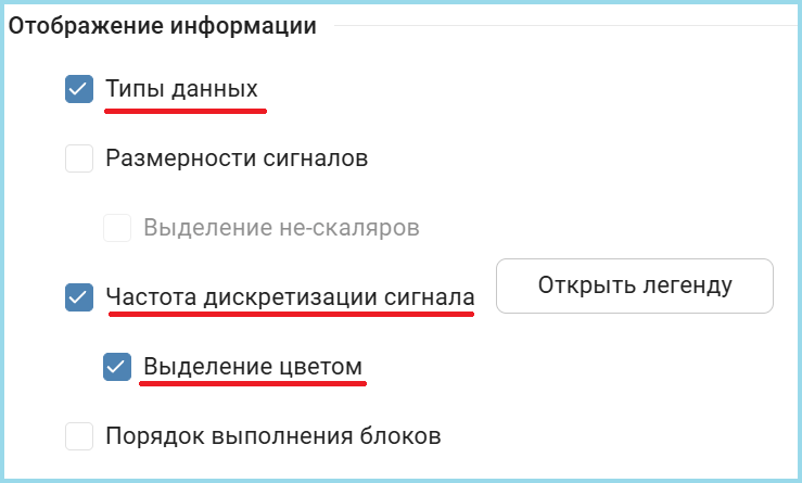
The calculation model supports the same functionality as the system version, but in a format suitable for hardware implementation.
Main features of the model:
- All calculations are performed with a fixed point
- Original mathematical formulas are preserved
- Added pipelining for vector operations
- The output signals are ready for Verilog code generation
To verify the correctness of the created model, it is run and then the results are compared with the original example.
run_model("model")
println("")

P_sim = (collect(simout["model/P"])).value[end]
m_sim = (collect(simout["model/m"])).value[end]
S_sim = (collect(simout["model/S"])).value[end]
S_sim_2 = (collect(simout["model/S"])).value[end-1]

println("Perimeter P = $P_sim")
println("Middle line m = $m_sim")
println("Area S = $([S_sim, S_sim_2])")
The values obtained completely match the results of the system model. The successful coincidence of the results confirms that the fixed-point model correctly implements the algorithm for calculating trapezoid parameters and is ready to generate hardware code.
Code generation and custom templates
Custom Templates
When developing hardware models, there may be a situation where the blocks used do not support automatic code generation. This can happen for various reasons: the block is custom, has specific functionality, or is simply not implemented in the target code generation system.
For such cases, Engee provides a mechanism for custom generation templates with the extension .cgt. These templates allow you to define how a specific block type should be converted into the target hardware description language.
Key features of the approach:
- Macro substitutions —
$(...)заменяются на реальные значения из модели - Условная генерация — логика зависит от свойств сигналов (разрядность, тип)
- Отдельные функции для повторяющихся операций
- Явное управление типами данных
Этот механизм обеспечивает гибкость при работе со сложными или специализированными блоками, позволяя создавать эффективные аппаратные реализации даже для компонентов, не имеющих встроенной поддержки генерации кода, теперь рассмотрим конкретный пример шаблона для блока умножения (Product), шапка для любого шаблона идентичная.
read_v("$(@__DIR__)/product.cgt")
Заголовок
//! BlockType = :Product
//! TargetLang = :Chisel
BlockType = :Product— указывает, что шаблон применяется к блокам типа "Product" (умножение)TargetLang = :Chisel— генерирует код на языке Chisel (Scala-based HDL), он является промежуточным звеном при генерации Verilog из моделей Engee.
Секция определений (@Definitions)
//! @Definitions
val $(output(1)) = Wire($(show_chisel_type(output(1))))
- Создаёт выходной провод (
Wire) с типом, соответствующим выходному сигналу $(output(1))— macro substitution for the name of the first output port$(show_chisel_type(...))— функция, возвращающая тип данных в синтаксисе Chisel
Секция шага генерации (@Step)
/*! @Step
function cast(sig)
    ".asTypeOf(FixedPoint($(sig.ty.bits).W,$(sig.ty.fractional_bits).BP))"
end
- Определяет вспомогательную функцию
cast() - Добавляет приведение типа для сигналов фиксированной точки в Chisel
$(sig.ty.bits)and$(sig.ty.fractional_bits)— извлекают разрядность из метаданных сигнала
Условное приведение типов результата
function maybe_cast_res_begin()
    output(1).ty.fractional_bits == 0 ? "(" : ""
end
function maybe_cast_res_end()
    output(1).ty.fractional_bits == 0 ? ").asSInt" : ""
end
- Условные функции для обработки целочисленных результатов
- Если дробная часть равна 0, результат преобразуется в знаковое целое (
.asSInt) - Оборачивает выражение в скобки при необходимости приведения типа
Основное выражение генерации
$(output(1)) := \
  $(maybe_cast_res_begin())\
    $(input(1))$(cast(input(1)))*$(input(2))$(cast(input(2)))\
  $(maybe_cast_res_end())
- Generates a multiplication operation:
выход := вход1 * вход2 - Adds type conversions for both inputs, if necessary
- Handles conditional conversion of the result type
Code generation
To generate code from the model, you need to select the target language of the generator, in our case it is Verilog.
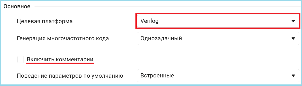
The next stage is the generation of hardware code in the Verilog language. To do this, use the function engee.generate_code(), with the following parameters:
| Parameter | Appointment | Example |
|---|---|---|
| The first | The path to the model file | "$(@__DIR__)/model.engee" |
| Второй | Выходная директория для кода | "$(@__DIR__)/V_Code" |
| Third | Name of the subsystem being generated | subsystem_name="trapeze_calculator" |
You can also generate the code by right-clicking on the subsystem block.

engee.generate_code(
    "$(@__DIR__)/model.engee",
    "$(@__DIR__)/V_Code",
    subsystem_name="trapeze_calculator"
)

read_v("$(@__DIR__)/V_Code/model_trapeze_calculator.v")
Generated module model_trapeze_calculator It is a compact hardware implementation of an algorithm for calculating trapezoid parameters. The code has a purely combinational logic, calculating all three parameters in one clock cycle.
The module accepts five 16-bit inputs (bases, height and sides) and generates three 16-bit outputs (centerline, perimeter, area). All calculations are optimized: the sum of the bases is calculated once with repeated use, division by 2 is performed by shifting, and multiplication for the area is implemented with an expansion of the bit depth to 24 bits to prevent overflow.
The code generator effectively transformed the algorithmic model into a hardware description with optimal use of resources, preserving the accuracy of fixed-point calculations and ensuring minimal signal delay.
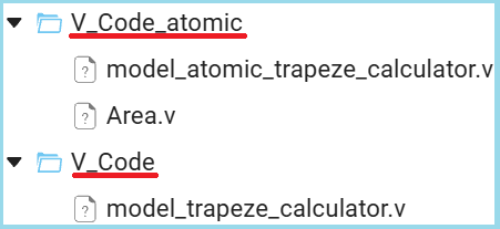
Atomic subsystems
Atomic subsystems are functional blocks in Engee models that, when generating code, are considered as independent, self—sufficient modules with clear I/O interfaces.
Unlike the previous monolithic version, where all calculations were concentrated in a single module, the atomic approach divides the functionality into logically independent components. The figure below shows how to create such a subsystem.
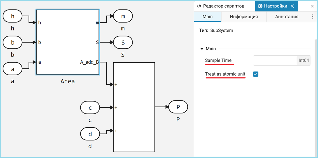
The algorithm is divided into two specialized modules:
Area— calculates the sum of the bases, the median line and the areamodel_atomic_trapeze_calculator— the upper level, which adds a perimeter calculation
engee.generate_code(
    "$(@__DIR__)/model_atomic.engee",
    "$(@__DIR__)/V_Code_atomic",
    subsystem_name="trapeze_calculator"
)

read_v("$(@__DIR__)/V_Code_atomic/model_atomic_trapeze_calculator.v")
read_v("$(@__DIR__)/V_Code_atomic/Area.v")
Despite the structural differences, both versions generate hardware identical results. The division into modules is a purely organizational improvement without affecting performance.
The modular approach becomes critically important when developing complex systems where different units can work on individual components in parallel. It also simplifies verification by allowing each unit to be tested in isolation, and facilitates debugging due to clear boundaries of responsibility between components.
Testing the generated code: verification tools
After the hardware code is generated, it must be thoroughly checked for correct operation. There are two main verification tools available in Engee. Both tools complement each other: Verilator is ideal for quick verification of functionality at early stages, while Icarus Verilog is indispensable for detailed time verification and preparation of final tests before synthesis. Using both methods guarantees maximum reliability of the generated code.
Verilator
Verilator is a high—performance simulator that converts Verilog code into optimized C++/C models. Its key features:
- C code generation: Verilog is translated into an equivalent C program
- Integration with the model: testing is performed directly inside the Engee environment
- Automation: does not require manual writing of the test environment
- High speed: simulation through compiled C code is significantly faster than interpreted solutions
The advantage of Verilator is the ability to quickly verify the generated code without the need to create additional test environments.
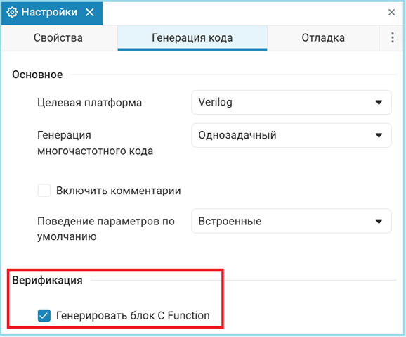
To automatically generate the C-function, we need to enable this setting in the code generation parameters.
Next, when generating the code, a script will be automatically created to generate a model with a C-function block, in our case the file is called model_trapeze_calculator_verification.jl let's run it and look at the results.
include("$(@__DIR__)/V_Code/model_trapeze_calculator_verification.jl")
As we can see, the model was created automatically, then we copy the input parameters from the original model and compare the results.
run_model("model_verification")
println("")

P_sim_C = (collect(simout["model_verification/test.P"])).value[end]
m_sim_C = (collect(simout["model_verification/test.m"])).value[end]
S_sim_C = (collect(simout["model_verification/test.S"])).value[end]
S_sim_2_C = (collect(simout["model_verification/test.S"])).value[end-2]

println("Perimeter P = $P_sim_C")
println("Middle line m = $m_sim_C")
println("Area S = $([S_sim_C, S_sim_2_C])")
As we can see, the results are identical to the original model, from which we can conclude that the generated code works exactly the same as the original model.
Icarus Verilog
Icarus Verilog is an interpretive simulator that executes Verilog code directly. Its distinctive features:
- Direct interpretation: the code is executed without intermediate conversion
- Requires a testbench: it is necessary to create a complete test environment on Verilog
- Detailed debugging: allows deep analysis of time charts
- Standard Compatibility: strict compliance with Verilog standards
This approach provides a more accurate match to the actual hardware behavior, but requires additional efforts to create a test environment.
read_v("$(@__DIR__)/tb.v")
This testbench performs a full check of the generated module. model_trapeze_calculator using the Icarus Verilog simulator.\
The testbench initializes the system with an active reset and input data in a fixed-point format (8-bit shift for the fractional part). After removing the reset, after 15 time units, sequential testing is performed for two trapezoid height values: first for h=4, then for h=5.
A shift is used to work with fixed point numbers. <<8, and the conversion of the results back to decimal format is done via $itor($signed(...))/256.0. The clock signal is generated with a period of 10 time units, and time delays control the sequence of test actions.
The test bench allows you to verify the correctness of calculations for different input data, check the system's response to dynamic parameter changes, and verify that the fixed-point format conversion is correct. All results are displayed in a convenient formatted form via the system function $display.
The testing process includes compiling and executing Verilog code, followed by processing the output data. Function extract_verilog_parameters analyzes the simulation output and extracts the calculated trapezoid parameter values for both heights.
run(`iverilog -o sim tb.v model_trapeze_calculator.v`)
output = read(`vvp sim`, String)
m_verilog, P_verilog, S4_verilog, S5_verilog = extract_verilog_parameters(output);
println(output)
The values obtained completely match the reference results of the system model, which confirms the correctness of the generated Verilog code.
Conclusion
This example demonstrates a practical approach to generating verified hardware code in the Verilog language using the Engee platform. The full development cycle is shown, from the algorithmic model to the health check of the generated code. Below is a script for comparing all the results of this work.
using DataFrames
df = DataFrame(
    Тест = ["Julia Script", "The Engee model", "Verilator's C-code", "Verilog Testbench"],
    P = [P, P_sim, P_sim_C, P_verilog],
    m = [m, m_sim, m_sim_C, m_verilog],
    S_h4 = [S[1], S_sim, S_sim_C, S4_verilog],
    S_h5 = [S[2], S_sim_2, S_sim_2_C, S5_verilog]
)
Based on this table, we can draw the following conclusions:
-
The transition from floating-point numbers in the Julia script to a fixed point in the hardware implementation is performed without loss of accuracy for this algorithm.
-
All four methods produced identical results, which confirms the correctness of the code generator and verification tools.
-
Successful completion of tests through both intermediate C-representation (Verilator) and native Verilog simulation (Icarus) eliminates accidental coincidences.
The considered methodology of model-oriented design can be applied to the development of digital signal processing systems or control algorithms, where a combination of high-performance hardware implementation with the convenience of algorithmic modeling is required.
Using Engee and similar tools significantly reduces the entry threshold and speeds up development for FPGAs. Algorithmists and system engineers get the opportunity to participate directly in the creation of hardware accelerators, focusing on the logic and optimization of the algorithm, rather than on the routine and error-prone translation of algorithms to HDL. The approach shown is a bridge between high—level modeling and efficient hardware, providing reliability through automatic generation and strict verification.
Note
In this example, steps such as synthesis and implementation were intentionally omitted, as they directly depend on the hardware platform.
Synthesis (Synthesis) is the process of converting a description of a digital circuit in HDL (Verilog/VHDL) into a technological netlist — a list of specific logical elements (LUT, triggers, memory blocks) and connections between them. The synthesizer analyzes the code, optimizes logical expressions and maps them to the primitives of the target FPGA architecture. At this stage, it is determined which resources of the crystal will be used and how they are logically connected.
Implementation (Implementation) — the next stage is when the synthesized netlist is physically placed on a specific FPGA crystal. The process includes placement, which is the distribution of logical elements to specific physical cells of the chip, and routing, which is the establishment of real connections through programmable switches. The implementation directly depends on the specific FPGA model and generates a final bitstream for programming the device.
Manufacturers of FPGAs and development Environments
| Manufacturer | The main development environment | Key FPGA Series |
|---|---|---|
| AMD/Xilinx | Vivado Design Suite (for 7-series and later), ISE (for older series) | Spartan, Artix, Kintex, Virtex, Zynq, Versal |
| Intel | Quartus Prime Design Suite | MAX, Cyclone, Arria, Stratix, Agilex |
| Lattice Semiconductor | Lattice Diamond, Lattice Radiant | iCE40, MachXO, ECP5, CrossLink |
| Microchip | Libero SoC Design Suite | IGLOO, ProASIC3, PolarFire, RTG4 |
| Open Source | Yosys+ nextpnr (independent tools) | Support Lattice iCE40/ECP5, Xilinx 7-series |
Vivado and Quartus Prime are the most common professional environments that provide a full development cycle, from code entry to bitstream generation. Lattice offers free tools for its FPGAs, and the Yosys/nextpnr open stack allows you to work with some architectures without proprietary software. The choice of environment is determined by the specific FPGA.