Code generation for TI C2000 (Dimmer)
This demo discusses the development of the Engee model for a triac dimmer controlled by a Texas Instruments TMS320F28379D microcontroller.
Introduction
The purpose of this example is to implement a triac dimmer model in Engee, followed by code generation and execution on a Texas Instruments TMS320F28379D microcontroller. The device reproduces the operation of the pulse-phase control system (SIFU), which receives signals of the zero crossing of the mains voltage and the analog value of the output voltage. The output signal of the SIFU is the control pulses for the triac, offset by the opening angle of the triac.
Hardware part
The device that physically reproduces the operation of the model in this example is the LAUNCHXL-F28379D debugging board based on the TMS320F28379D microcontroller from the C2000 family from Texas Instruments. The following inputs/outputs of the debugging board are used for this example:
- Connector J5, pin 41 "3V3" - 3.3 V power supply.
- Connector J7, pin 61 "5V" - 5 V power supply.
- Connector J3, pin 22 "GND" - common.
- Connector J4, pin 40 - digital input GPIO 0 Zero crossing signal interrupts.
- Connector J3, pin 30 - analog input ADCIN A0 Voltage settings.
- Connector J1, pin 2 - digital output GPIO 32 SIPHON pulses.
In addition to the control function, the debugging board provides electrical power to the electronic circuit shown in the figure below.
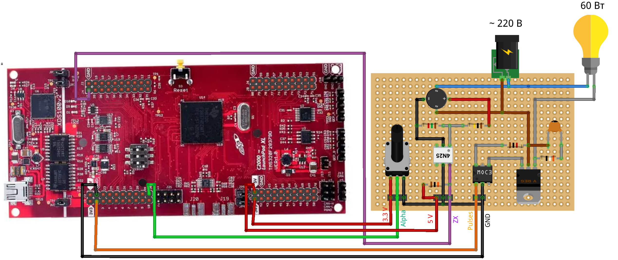
The voltage is set using an analog "Alpha" signal from a 10 kOhm potentiometer, which also receives 3.3 V power from the debugging board.
The zero crossing signal "ZX" is generated by the optotransistor 4N25 based on the rectified mains voltage signal from the resistor voltage divider. A single-phase diode bridge is used to rectify the mains voltage.
The pulse signal of the SIFU "Pulses" enters the input of the optosimistor MOC3023, which generates signals for opening the power triac BT136-800E. This triac is used to regulate the voltage on the load, an incandescent lamp with a power of 60 watts.
A protective RC circuit with a resistance of 39 ohms and a capacity of 1 nF is connected between the power outputs of the triac.
A Hantek DSO digital oscilloscope is used to monitor the control process.
To assemble the hardware described in this example, we strongly recommend that you follow the requirements of the regulations in the field of occupational health and safety, electrical safety, and fire safety. In the absence of the necessary competencies, personal protective equipment, serviceable and safe components, we strongly recommend contacting specialists in the relevant field.
Description of the model
In the model of this example dimmer_model.engee Two counter-parallel thyristors (blocks) are used as a triac. Thyristor (Piecewise Linear)), a resistor with a resistance of 1 kOhm is used as the load. A mains voltage with an effective value of 220 V and a frequency of 50 Hz is modeled on the contacts of the regulated voltage source unit. The voltage drop is measured in the circuit V_load and the current I_load.
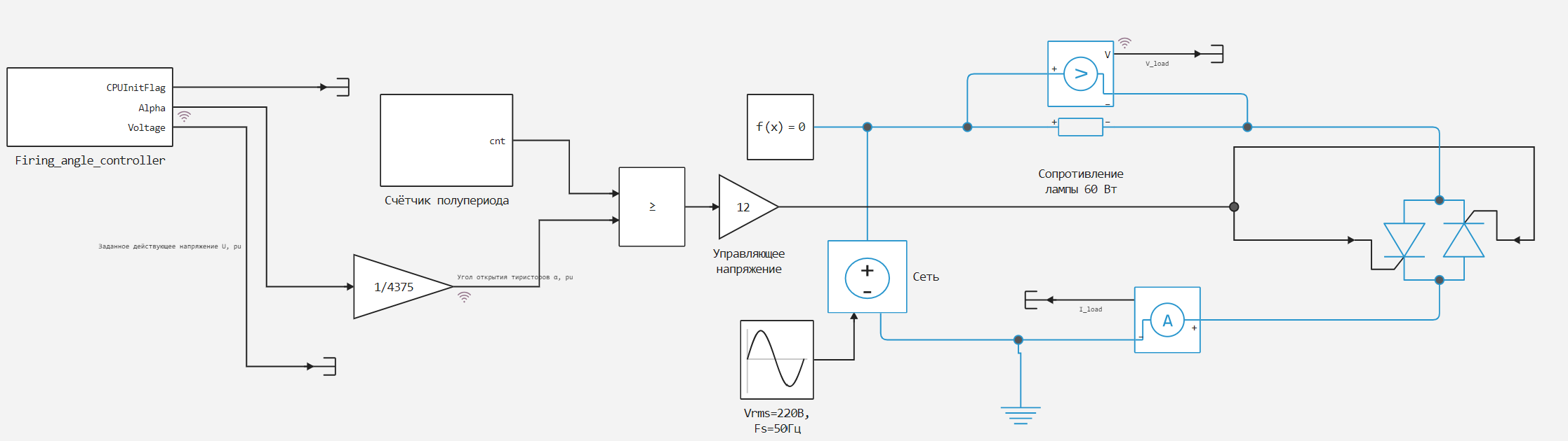
The triac is opened by comparing the current value of the half-cycle counter of the mains voltage and the opening angle of the thyristors α. In this case, the control signal must be converted from the logic level to the voltage level of the control input. The opening angle of the thyristors is set by a pulse-phase control system. Firing_angle_controller. Also, for simulation purposes, a signal of a given operating voltage U is output from this subsystem.
Pulse-phase control subsystem
Subsystem Firing_angle_controller It is used not only for modeling the dimmer control system, but also for code generation. The operation of the microcontroller and its peripherals is determined by the code written in the blocks C Function:
CPU_Init- initializes the central processor of the controller and the peripheral interrupt module.XINT1- configures and activates the hardware interrupt module, including determining the interrupt signal channel, activating event, and interrupt handler.ADC_A0- configures and initializes the ADC channel A0 and the conversion start trigger (SOC), polls the ADC channel to obtain a new set voltage value.GPIO_32U_Output- configures the GPIO 32 pin as a digital output, generates an output signal with a preset delay.
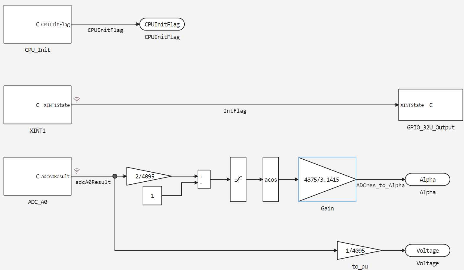
In addition to the blocks for interaction with the controller's peripherals, the subsystem contains blocks for converting the signal of a given voltage adcA0Result.
The output signal of a 12-bit ADC is a preset voltage adcA0Result in the range [0, 4095]. In this case, the control signal is the opening angle of the thyristors. Alpha with the corresponding range of values [4375, 0], determined by the function:
In general, the management system works as follows. After startup, the microcontroller configures and starts the used peripherals. Then, in an endless cycle, a new value of the set voltage is expected and read. adcA0Result. In case of an interrupt event INT_XINT1 (zero crossing by mains voltage) the processor calls an interrupt service routine that sets the interrupt flag XINT1State. After that, the interrupt stops, and the main program executes the interrupt flag condition loop. When the condition cycle is fulfilled, a delay is formed equal to the opening angle of the triac to ensure the voltage set at the time of the interruption. After the delay has passed, a control pulse is generated at the digital output of the controller, the triac opens, the interrupt flag is reset, and the processor returns to waiting for a new set voltage value.
A detailed description of the principles of operation of the peripheral interaction units is given in the relevant comments to the code. Next, we will focus on some specific issues of the management system.
Pluggable files
For correct code generation and further correct compilation of the generated files, it is necessary to connect the files used in the main program to initialize the microcontroller's peripherals.
These are the files device.h and driverlib.h from the folder device of this project. They are not used in modeling, and are only needed to connect them in the generated files.
They are connected in the block settings. XINT1, tab Build options:
.png)
Interrupt handling
In the block XINT1 The interrupt module is being configured. The contents of the tabs are of the greatest interest here </> StartCode and </> TerminateCode.
In the tab </> StartCode The hardware interrupt module is configured and enabled. The Interrupt Service Procedure (ISR) is also connected here. This happens by calling the function:
Interrupt_register(INT_XINT1, dimmer_model_Firing_angle_controller_term);
The second argument of the function - dimmer_model_Firing_angle_controller_term and performs the role of ISR. It is a subsystem termination function. Firing_angle_controller the developed model that will result from code generation. In this model, all block termination tabs are C Function, except for the block XINT1, are empty.
In the tab </> TerminateCode The interrupt service procedure is described.
It consists in changing the value of the interrupt flag. XINT1State and clearing the interrupt accumulator.
Triac opening angle
The current value of the interrupt flag in the main program cycle is passed to the block GPIO_32U_Output, where a triac opening pulse is formed in a conditional cycle with a given delay.
Pulse generation is described by the code provided in the tab </> OutputCode the block:
    //
    // Проверка флага прерывания
    //
    if(XINT1Flag){
           //
           // Установка отсчёта в точку естественной коммутации
           //
           DEVICE_DELAY_US(500);
           //
           // Формирование задержки на величину угла открытия
           //
           DEVICE_DELAY_US(dimmer_model_Firing_angle_controller_Y.Alpha);
           //
           // Управляющий импульс
           //
           GPIO_writePin(32U, 1);
           DEVICE_DELAY_US(15);
           GPIO_writePin(32U, 0);
           //
           // Сброс флага прерывания
           //
           XINT1State=!XINT1State;
           }
If there is an interrupt flag XINT1Flag The condition is fulfilled in this block. First of all, a delay is formed here to transfer the triac opening angle to the natural switching point. This is necessary due to the fact that the hardware detection of the zero crossing by the 4N25 optocoupler occurs approximately 1 ms earlier than the actual zero crossing at the natural switching point.
This is followed by a delay of the opening angle of the triac. At the same time, the amount of delay dimmer_model_Firing_angle_controller_Y.Alpha - this is the output variable of the subsystem Firing_angle_controller, obtained as a result of code generation.
After passing the delay, a control pulse is generated and the state of the interrupt flag is inverted. XINT1State.
Simulation results
To simulate the triac regulation of the output voltage in the unit ADC_A0 A linearly increasing output value of a given operating voltage is formed.
To simulate the regulatory process, we will load and run the model dimmer_model:
if "dimmer_model" in [m.name for m in engee.get_all_models()]
    m = engee.open( "dimmer_model" );
else
    m = engee.load( "$(@__DIR__)/dimmer_model.engee" );
end

data = engee.run(m);
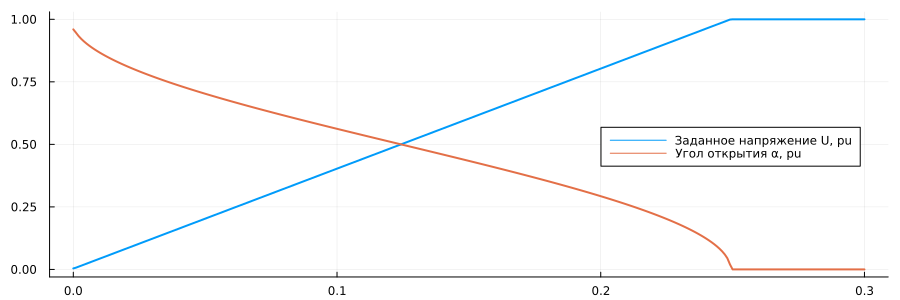
From the obtained simulation data, we will plot graphs of the set operating voltage and the generated opening angle of the thyristor in conventional units.:
using Plots
gr( format=:png )
plot(data["Set operating voltage U, pu"].time,
     data["Set operating voltage U, pu"].value,
     label="Set voltage U, pu", size=(900,300),
     lw=2, legend=:right)
plot!(data["Opening angle of thyristors α, pu"].time,
      data["Opening angle of thyristors α, pu"].value,
      label="Opening angle α, pu", lw=2)
Let's plot the voltage drop across the load:
plot(data["V_load"].time, data["V_load"].value,
     label="Voltage U, pu", size=(900,300),
     lw=2, legend=:topleft)
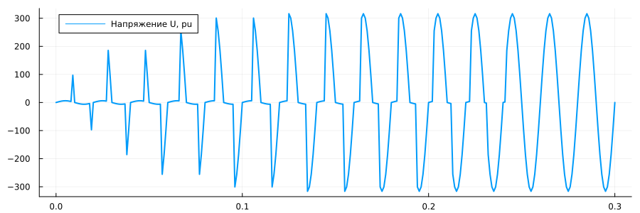
As can be seen from the graphs obtained, according to the setting of the operating voltage, the correct formation of the opening angle of the triac occurs.
Code generation
We will generate a code from a subsystem with a pulse-phase control algorithm. Firing_angle_controller:
engee.generate_code( "$(@__DIR__)/dimmer_model.engee",
                     "$(@__DIR__)/TI_dimmer_code";
                     subsystem_name="Firing_angle_controller" )
For the SIFU to work correctly, the following adjustments must be made in the generated Si falas:
In the header file dimmer_model_Firing_angle_controller.h:
Let's replace the keyword extern for the function prototype extern void dimmer_model_Firing_angle_controller_term();
on the keyword interrupt so that this function is perceived by the compiler as an ISR.
In the file dimmer_model_Firing_angle_controller.c:
Add the directive line at the very beginning of the code. #define LAUNCHXL_F28379D to define a macro LAUNCHXL_F28379D. This macro is necessary for performing conditional compilations limited in generated files by directives. #ifdef...#else...#endif.
Main program and project
The main program code is shown in the file dimmer.h. It connects the header files necessary for the project (including the generated one), declares global variables, and calls the initialization and calculation functions of the model.
To program the controller, the Code Composer Studio 12.7.1 development environment (hereinafter referred to as CCStudio) from Texas Instruments is used.
To start working with the developed program and controller, you need to follow the steps for setting up the environment, connection, and project, namely:
- selecting the project workspace;
- selection of the debugging board, processor and its characteristics;
- Connection selection;
- create an empty project
dimmer.
Add the main program file and the generated files to the created empty project in the CCStudio environment. The project tree will look like this:
.png)
Executing code on a microcontroller
After adding the files to the project, follow these steps:
- connect the debugging board to the computer via USB;
- run the build of the project in CCStudio (Build) for the selected processor and memory area - this project is CPU1_RAM;
- run the debugging of the project (Debug), as a result of which, among other things, the code will be loaded into the processor;
- launch the program (Run).
After starting the program, you can observe a change in the brightness of the incandescent lamp, the adjustment of the variable opening angle of the triac in CCStudio and the oscillogram of the voltage drop across the lamp. The recording of the dimmer operation is presented in the file dimmer.gif this example.
To plot the triac opening angle in CCStudio, add a variable FiringAngle go to the variable viewport "Expressions" and select plotting ("Graph") for this variable. In the "Single Time -0" plotting window, you can enable continuous updating, adjust the frequency of polling values and the size of the value buffer.
The DSO Controller program is used to transfer the waveforms taken by the Hantek DSO digital oscilloscope to a computer.
Conclusion
In this demo, a triac dimmer model was developed with subsequent generation of the pulse-phase control system code for the TMS320F28379D microcontroller. The results of the control system are shown in the Engee model using physical modeling units and on a triac dimmer with an incandescent lamp load.