Direct current power transmission based on thyristor converters
This example shows a DC power transmission model based on 12-pulse thyristor converters with a capacity of 1000 MW with nominal parameters of 500 kV, 2 kA, 50/60 Hz.
Description
The model considers a 1000 MW DC power transmission with a rated voltage of 500 kV and a current of 2 kA. It is designed to transfer power from an alternating current transmission system of 500 kV, 5000 MVA, 60 Hz to an alternating current receiving system of 345 kV, 10,000 MVA, 50 Hz. The model's appearance:
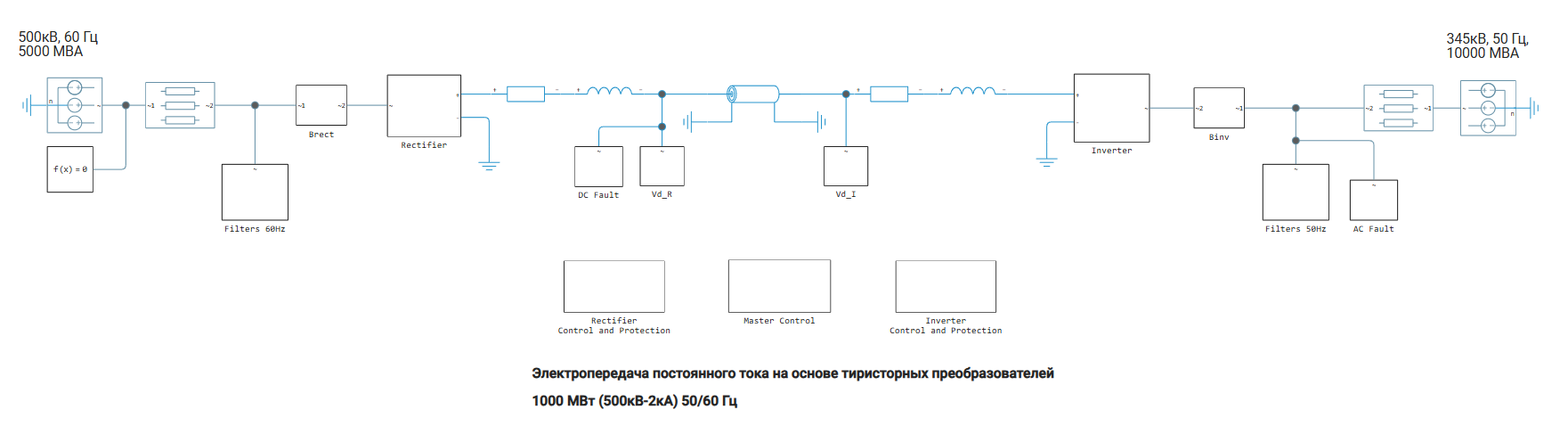
Two converter substations are installed at the ends of the power transmission: a rectifier and an inverter. The rectifier and the inverter are made according to a 12-pulse circuit based on two 6-pulse thyristor bridges connected in series. The converter substations are connected by a 300 km long DC line represented by a U-shaped model of the line. Two smoothing reactors with an inductance of 0.5 Gn are also included in the DC circuit.
Devices for regulating the transformation coefficients of converter transformers are not taken into account in the model; the transformation coefficients are considered fixed. In the rectifier and inverter subsystems, you can open the transformer blocks and see the coefficients applied to the primary winding voltage: 0.90 on the rectifier side and 0.96 on the inverter side.
The reactive power consumed by valve converters is compensated by filter compensating devices. Capacitor banks, 11th and 13th harmonic filters, and a high-pass filter are installed on each side. The total capacity of the filter compensating devices is 600 Mvar on each side.
The model provides two switches used to create emergency modes: a short circuit on the AC side of the inverter substation and a short circuit in the DC line on the side of the rectifier substation.
Each converter has DC circuit protection functions. On the rectifier side, the short circuit protection in the DC line detects an accident and forcibly switches the control angle α to the range of the inverter mode. This is necessary to extinguish the emergency current.
On the inverter side, protection is provided against overturning of the inverter, that is, against valve switching failure. In case of damage in the AC network, this protection reduces the maximum allowable value of the control angle α, thereby increasing the switching margin and reducing the likelihood of the inverter tipping over.
The AC undervoltage detection units block the protection of the DC circuit when detecting a voltage drop on the AC side. This is necessary to ensure that the DC line protection does not malfunction in case of accidents in the adjacent AC system.
The control unit (Master control) starts and stops the converters, and also generates a smooth increase and decrease in current settings. The power unit and the control system have a calculation step of Ts = 50 microseconds. In the PreLoadFunc callback, variables with basic system parameters are set.
Simulation
A start-up and steady-state scenario is set in the control unit. Then, the setting of the rectifier current and the setting of the inverter voltage are stepwise changed, which makes it possible to evaluate the dynamic properties of the regulators. After that, the shutdown sequence starts: the power transmitted over the DC line gradually decreases, and then the converters are blocked.
After performing the simulation, you can open the Signal Visualization window and look at the results. The graphs show the DC line voltage, where 1 AC corresponds to 500 kV, and the DC line current is the measured and setpoint values, where 1 AC corresponds to 2 kA.
Start and stop
In the Master Control unit, the converters are unblocked and started up by smoothly changing the current setting of the rectifier and inverter.
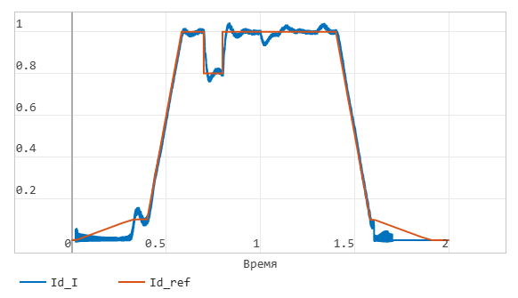
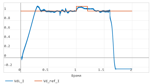
At time t = 0.02 s, when the converters are unlocked, the current setting begins to increase smoothly to a minimum value of 0.1 oe in 0.3 s. The rise rate is 0.33 oe/s. By the end of this first acceleration phase, at t = 0.32 s, the DC line is charged to the rated voltage, and the DC voltage is released to a steady value.
At time t = 0.4 s, the current setting increases from 0.1 oe to 1 OE, which corresponds to 2 kA, in 0.18 s. The rate of change of the target is 5 oe/s. By the end of the starting sequence, at t = 0.58 s, the DC current reaches a steady value.
After the start—up is completed, the rectifier operates in current regulation mode, and the inverter operates in voltage regulation mode. In steady-state mode, the control angles α are 16.5° on the rectifier side and 143° on the inverter side. The margin angle γ is measured on the inverter side. In steady state, its minimum value is in the range of 22-24°.
The operating mode of the control system is displayed as an integer (controller Mode output) from 0 to 6:
0 — the converter is locked;
1 — current regulation;
2 — voltage regulation;
3 — limitation of the minimum angle α;
4 — limitation of the maximum angle α;
5 — forced or constant value of the angle α;
6 — adjustment of the angle γ.
At time t = 1.4 s, the stop sequence is started: The current gradually decreases to 0.1 oe. At time t = 1.6 s, a forced value of the angle α is set on the rectifier side, which leads to current damping. On the inverter side, the forced value of the angle α reduces the DC voltage. At time t = 1.7 s, the control pulses of both converters are blocked.
Inverter current graph:
Inverter voltage graph:
Transient characteristics of current and voltage regulators
In the Master Control block, make sure that the Enable Ref switch is on. The Current Step is in the upper position. This switch is used to apply a stepwise effect to the set current value. It is also necessary to make sure that the step-by-step effect on the voltage setting is enabled in the inverter control unit.
At time t = 0.7 s, the set current changes stepwise by -0.2 OE: the value decreases from 1 oe to 0.8 oe. At time t = 0.8 s, the current setpoint returns to the initial value of 1 oe. The current stabilizes in about 0.1 s.
In addition, stepwise effects are applied to the voltage setpoint of the inverter: -0.1 OE at time t = 1.0 s and +0.1 oe at time t = 1.1 s.
Short circuit in the DC line on the rectifier side
It is necessary to disable stepwise effects on current and voltage settings. To do this, the corresponding switches in the Master Control and Inverter Control blocks are moved to the lower position.
In the DC Fault block, the switch state must be changed so that a short circuit is created at time t = 0.7 s. The simulation end time should be reduced from 2 s to 1.4 s. Short circuit protection in the DC line on the rectifier side is enabled by default.
When a short circuit occurs, the DC current increases rapidly to 2.3 OE, and the DC voltage on the rectifier side drops to zero. This voltage drop is detected by a current setting limiter that depends on the DC voltage. As a result, the current setpoint on the rectifier side is reduced to 0.3 oe. In this case, the emergency current continues to flow through the damage site.
Then, at time t = 0.77 s, the DC protection forcibly sets the rectifier control angle α to 166°. This occurs after detecting a DC voltage drop below 0.5 ohms for more than 70 ms. In this mode, the rectifier switches to the inverter mode of operation.
The DC line voltage becomes negative, and the energy stored in the line is returned to the AC transmission system. This leads to a rapid decrease in the emergency current at its closest transition through zero. Then, at time t = 0.87 s, the forced setting of the angle α is removed, and the normal values of voltage and DC current are restored in about 0.4 s.
Single-phase ground short circuit on the AC side of the inverter
In the DC Fault block, change the state of the switch so that the short circuit in the DC line is disabled. Then, in the Fault block A-G, it is necessary to change the state of the switch so that at time t = 0.7 s a single-phase earth short circuit with a duration of 100 ms is applied.
The subsystems for detecting low AC voltage in the rectifier and inverter protections, as well as the inverter rollover protection, are enabled by default. After that, you need to run the simulation again.
During an accident, voltage and DC currents fluctuate with a frequency of 120 Hz. After disconnecting the damage at time t = 0.8 s, the current setting limiter is activated, depending on the DC voltage, and reduces the current setpoint to 0.3 O. E. The system is restored in about 0.35 s after the accident is eliminated.
The AC undervoltage Detection Subsystem (LACVD) detects an accident and blocks short circuit protection in the DC line. This is necessary because the DC protection should not detect damage in the DC line when there is a voltage drop caused by an accident on the AC side.
Attention should be paid to the output signal A_min_I of the inverter rollover protection. This signal reduces the maximum allowable value of the control angle α in order to increase the switching margin during an accident and during recovery after it.
If you disable the CFPREV protection of the inverter by unchecking the ON State checkbox in its dialog box and running the simulation again, you can see a change in the recovery time of the DC power transmission. In this case, the inverter overturns during recovery.
Overturning of the inverter is an emergency mode of operation of the inverter associated with a violation of the valve switching process due to an insufficient angle of the switching margin γ. As a result, the current does not have time to switch from the off valve to the on one, which leads to a breakdown of the inverter mode and a temporary transition of the converter to the rectifier mode. A characteristic feature of tipping is a sharp decrease in the DC voltage on the inverter side and an increase in the current in the DC circuit.