Diesel-battery marine power plant: controlling the torque of the propeller
This example presents a multi-domain physical 1-D model of a marine power plant that combines a diesel generator set, a battery pack, power electronics, and a permanent magnet synchronous motor (DSM) that drives a propeller.
The model allows us to study interrelated electrical, electromechanical and hydrodynamic processes during acceleration and maneuvering of the vessel, as well as to develop algorithms for controlling the power plant and the torque of the propeller.
Model features
-
Checking the algorithms of joint control of the DSU and the battery
Investigation of acceleration and maneuvering modes of a vessel with power distribution between a diesel generator and an energy storage device. -
Fuel efficiency assessment
Analysis of the battery's effect on the diesel engine's operating mode and assessment of the potential reduction in fuel consumption due to the use of stored energy in transient modes. -
Adjustment of the propeller torque control law
Investigation of the dynamics of the system under various parameters of regulators and given laws of change of torque, rotation speed and power of the control system. -
Investigation of electromagnetic transients
Calculation of the behavior of electrical equipment in case of short circuits, load surges and surges, power supply changes and other emergency impacts. -
Investigation of the dynamics of propeller and ship acceleration
Consideration of the mechanical inertia of the drive, the attached masses, the moment of resistance of the propeller, the flow velocity, wave resistance and other hydrodynamic factors.
Introduction
Modern ships are complex technical systems in which the mechanical and electrical parts are closely interconnected. The increasing demands on energy efficiency, maneuverability and reliability of marine power plants are leading to the widespread use of diesel-electric complexes, battery energy storage systems and regulated electric drives.
Description of the model
-
Two DGS — the main sources of generation;
-
SNE — peak load compensation;
-
Basic AC load;
-
Switched AC load;
-
Switching load on the DC bus;
-
Cable lines;
-
Converters— rectifier and inverter;
-
SDPM — electric propeller drive;
-
The propeller is the mechanical load of the drive;
-
The mass of the vessel is taken into account when modeling acceleration dynamics;
-
Flow model — takes into account the influence of the incoming flow velocity on the propeller operation mode.
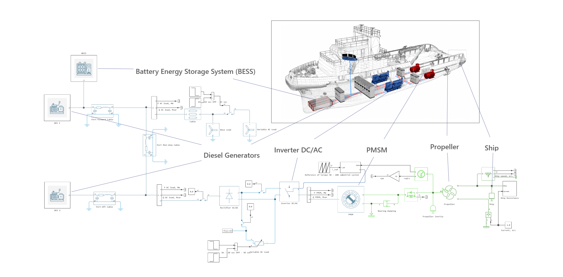
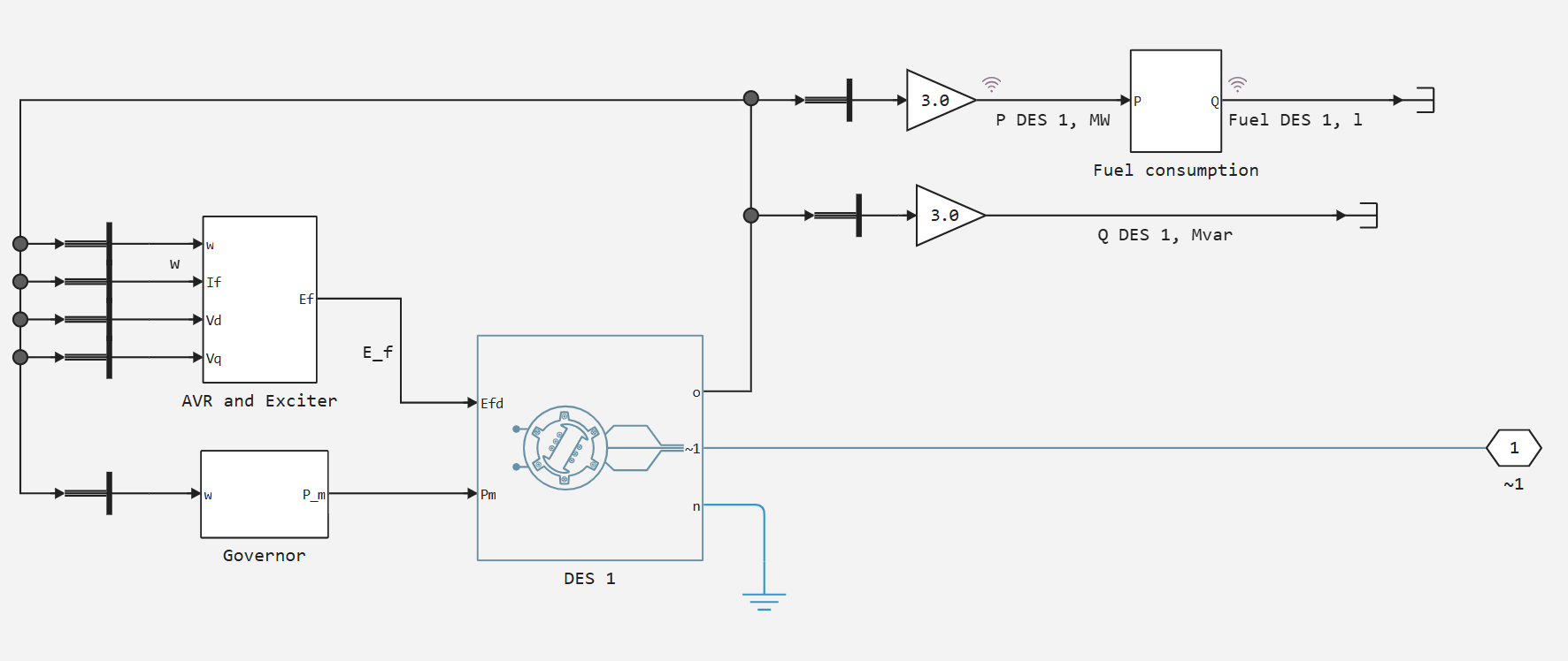
Description of the DSU model
The DSU model is presented in the form of a generator in phase координатах , diesel engine models with speed control, ARV-M and возбудителя:
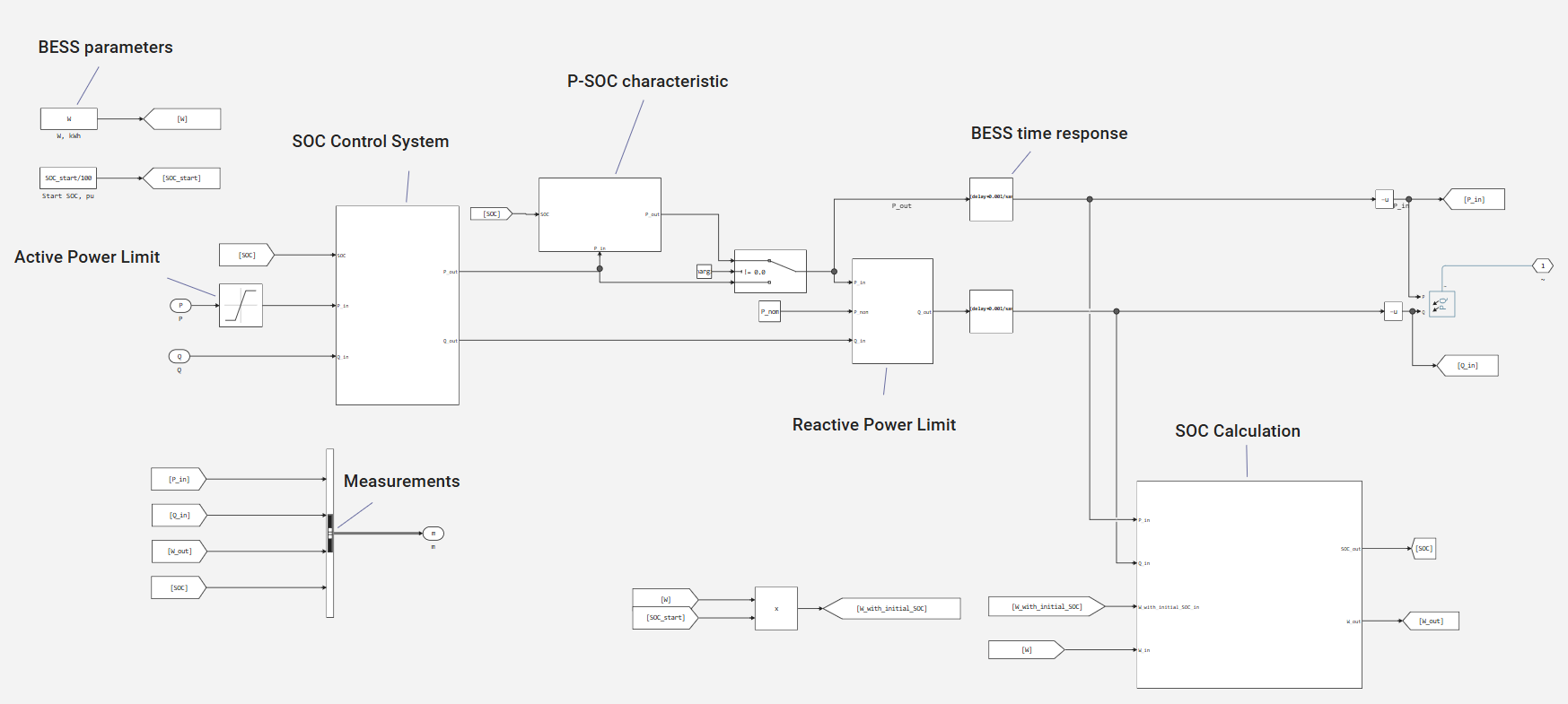
Description of the SNE model
The generalized SNE model as part of a marine power plant is as follows:
Description of the electric propeller drive model
The electric drive model includes an inverter, a control system, an ATM, a mechanical transmission, a propeller, and a ship motion model.
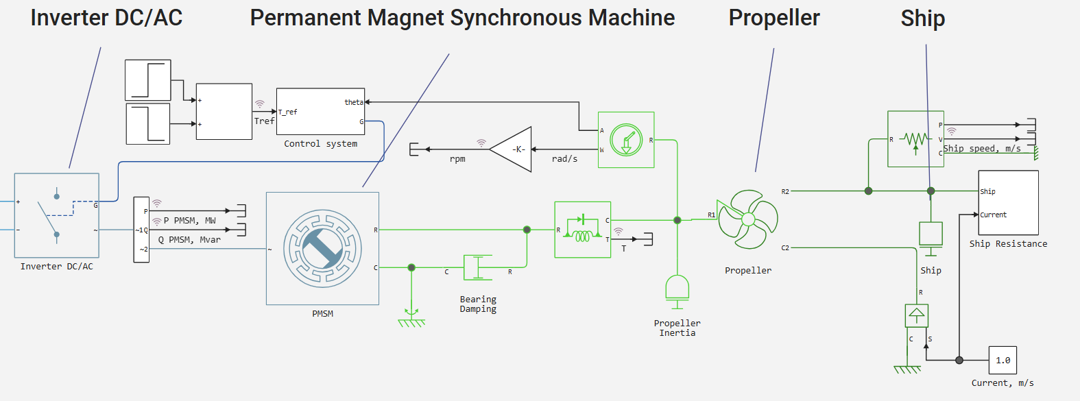
Electrical part
The SDM control is implemented on the basis of vector dq control. The set moment is converted into control actions along the longitudinal and transverse components of the current. The control circuits use PI regulators that generate the required control voltages. Next, the PWM signals are generated, which are supplied to the DC/AC power inverter. The inverter generates a three-phase voltage to supply the SDPM and regulates its electromagnetic torque and rotation speed.
Rotational and translational mechanics
The mechanical part of the model takes into account the inertia of the rotor and propeller, bearing damping and the mechanical load of the propeller.
The propeller is connected to the ship's motion model. When it rotates, a traction force is formed that ensures the movement of the vessel. The model also takes into account the water flow velocity, which determines the relative velocity of the incoming flow to the propeller and, accordingly, affects the thrust generated by the propeller and the moment of resistance.
The Ship Resistance unit calculates the oncoming resistance to the ship's movement. Depending on the speed of the vessel, the force of water resistance directed against movement is determined. This force creates an additional mechanical load on the propulsion system and directly affects the acceleration dynamics and steady-state speed of the vessel.
Simulation results
0 - 20 s — surge-reset AC load;
20-30 s — surge-reset DC load;
30-100 s — launch of the SDPM and acceleration of the propeller.
Power graph:
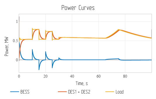
The graph shows that at the first (0-20 s) and second (20-30 s) intervals of the simulation, the SNE effectively smooths out the jumps in AC and DC loads. At the 30th second, the SDPM is launched, the ship accelerates.
Vessel speed graph:
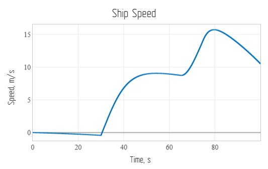
Up to 30 seconds, the ship is carried away by the current, the speed is negative.
Graph of the speed of rotation of the propeller:
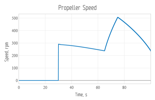
The graph shows the speed of rotation of the SDPM.
Timeline of the SDPM moment:
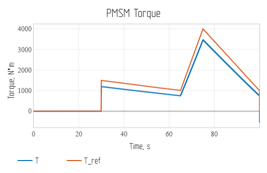
The graph shows two signals: the actual moment and the reference moment.
Graph of instantaneous fuel consumption of DSU 1 and 2:
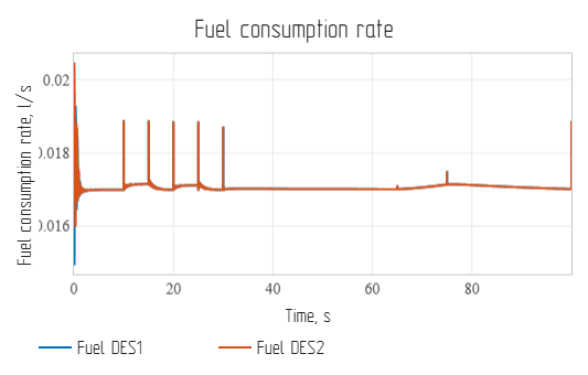
The graph shows the fuel consumption signals of each DSU. In 100 seconds of simulation, the DSU consumes ~1.5 liters of diesel fuel.
Conclusions
A digital model of a marine power plant based on DSU and SNE with an SDPM propeller drive has been developed. Based on the simulation results, it can be seen that the model reflects electromechanical processes, ship mechanics and hydrodynamics for testing transient modes and setting up automatic control.