Bergeron power line: dividing the power system model into parts
This demo project talks about the possibility of dividing the power system model into parts to speed up the calculation of the model using the [Connector Bergeron Line] block. (Three-Phase)](https://engee.com/helpcenter/stable/ru-en/fmod-electricity-lines/connector-bergeron-line-three-phase.html).
Introduction
When modeling large electric power systems (EES), high computational complexity becomes one of the main problems. The more generators, power lines, transformers, and other elements in the model, the more time it takes to calculate each step of the simulation.
This problem is especially critical in [real-time simulation] (https://engee.com/helpcenter/stable/ru-en/ritm/intro.html ), when the calculations of each step must be completed in a time not exceeding the specified simulation step.
One way to speed up calculations is to divide the power system model into several parts that can be calculated in parallel.
In this demo project, we will look at how to implement such separation in Engee using the Bergeron power line model.
Louis Bergeron: from pipelines to power lines
Louis Jean Baptiste Bergeron (March 10, 1876 — February 23, 1948) was a French entrepreneur, engineer and inventor.He is remembered for his practical, mathematical methodological approach to the study of hydraulic shocks in hydraulic pipeline systems, which he also showed to be useful in the study of electromagnetic voltage/current surges in electrical systems. His latest work, "From Hydraulic Shocks in Hydraulics to lightning discharges in Electricity," published posthumously, became a reference work in electrical engineering.
In electrical engineering, the use of the so-called "Bergeron equations" makes it possible to calculate phenomena бегущих волн in "long" conductors using numerical analysis. Герман В. Доммель used these "Bergeron equations" in software EMTP * in the late 1960s.*
As a rule, the Bergeron power line model should be chosen instead of the N-section if the length of the power line is sufficient for the propagation of waves (approximately at the speed of light) to pass along the entire length of the power line in one time step. This means that for a typical simulation step dt = 50 microseconds, a power line with a length of more than 15 km (the speed of light is divided by 50 microseconds, we get 15 km) should be represented by the Bergeron model, and not by the P-section.
The main feature of the Bergeron model is the presence of a physically determined delay in the propagation of an electromagnetic wave along the line. This feature allows you to divide the power grid into parts without introducing additional delays. We use the existing delay of the transmission line to enable two computing parts to work simultaneously.
For example, at a wave propagation speed of about 300,000 km/s, the travel time of a 300 km line is approximately 1 ms. If the simulation step is 50 microseconds, then the delay corresponds to 20 calculation steps.
The process of dividing the power system model into parts
- We take the model from the example "IEEE 9 Bus model with synchronous machines" and select the section along the power line along which we will divide the network.
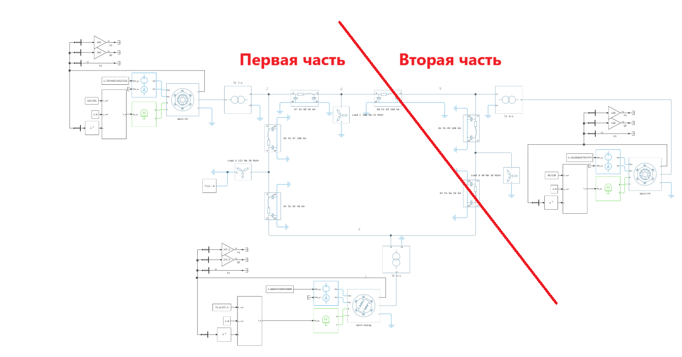
-
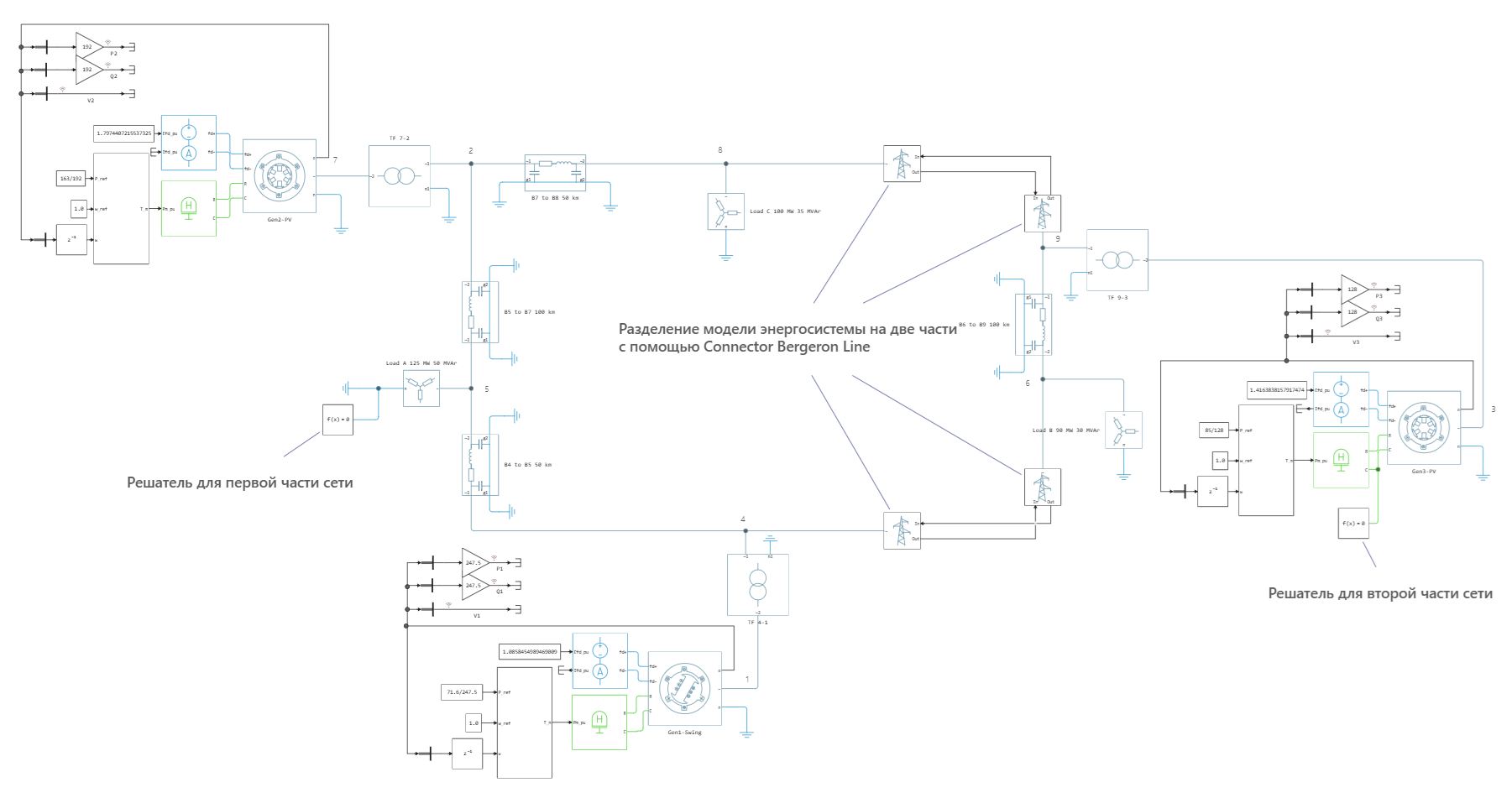
Replace the original power line blocks with [Connector Bergeron Line] blocks (Three-Phase)](https://engee.com/helpcenter/stable/ru-en/fmod-electricity-lines/connector-bergeron-line-three-phase.html):
Conclusions
The demo project considers a way to split the IEEE 9 bus physical model into parts using [Connector Bergeron Line] blocks. (Three-Phase)](https://engee.com/helpcenter/stable/ru-en/fmod-electricity-lines/connector-bergeron-line-three-phase.html).
Related documentation
- IEEE 9 Bus model with synchronous machines — the initial model of the power system