Zero-sequence directional current protection
Introduction
In the previous linked примере, the block ** of current directional (non-directional) protection of the zero sequence** (TNNP) was presented. The software control of the model was used to check its operation.
In this example, we consider conducting automatic testing of a set of two stages of the TNNP. For this purpose, the same model of the power system is used as in the previous example.
Description of the power system model
The scheme and parameters of the power system are presented below:
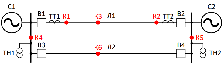
Parameters of the C1 power system:
The active resistance of the direct sequence is 0.393 ohms
The inductive resistance of the direct sequence is 4,276 ohms.
The active resistance of the zero sequence is 0.494 ohms
The inductive resistance of the zero sequence is 4.02 ohms
Equivalent EMF– 230 kV
The EMF phase angle is 10°
Parameters of the C2 power system:
The active resistance of the direct sequence is 4.85 ohms
The inductive resistance of the direct sequence is 25.604 ohms
The active resistance of the zero sequence is 10.607 ohms
The inductive resistance of the zero sequence is 53.347 ohms.
The equivalent EMF is 220 kV
The EMF phase angle is 0°
Parameters of lines L1 and L2:
Length 100 km
The resistivity of a straight line is 0.0958 +j 0.4038 ohms/km
The resistivity of the zero sequence line is 0.3471+ j 1.2432ohms/km
The specific capacity of the direct sequence is 2,642 µsm/km
The specific capacity of the zero sequence is 2,119 µsm/km
Automatic testing of relay protection
First, open the model and download it for a quick launch.:
example_path = @__DIR__; # We get the absolute path to the directory containing the current script
cd(example_path); # Go to the example directory

model_name = "ground_directional_overcurrent_relay_autotest.engee"
engee.open(model_name); # Opening the model
model = engee.load(model_name); # Download the model for quick access
Auxiliary functions
To implement automatic testing, it is proposed to wrap the code used in the implementation example ТНЗНП , into auxiliary functions, connect them into the main function for testing and organize a protection check cycle for all short-circuit points.
The first step is to create and describe auxiliary functions.
The function for obtaining the current protection settings specified in the model is shown below. It is necessary to control the excess of current settings.:
"""
    get_trip_values(path, protections...)

Auxiliary function for obtaining current settings and protection response time.

# Arguments
- `path::String`: the path to the model
- `protections::Vararg{String}`: list of protection names

# Returns
A tuple of tuples `(I_trip::Float64, t_trip::Float64)` for each protection passed.
"""
function get_trip_values(path::String, protections::Vararg{String})
    # Inside the list, [] iteratively iterates through the transferred protections and requests the I_trip and t_trip parameters.
    trip_list = [(parse(Float64, engee.get_param(path * "/" * protection, "I_trip")),
                parse(Float64, engee.get_param(path * "/" * protection, "t_trip")))
                for protection in protections]
    return tuple(trip_list...)
end;
Before running each simulation, it is necessary to make sure that all short-circuit points in the model are disabled, except for the required one. To do this, a reset function is created that disables the short-circuit points transferred to it.:
"""
    reset_sc(sc_locations)

An auxiliary function for disabling all preset short-circuit points.

# Arguments
- `sc_locations::AbstractVector{String}`: a list of names (paths) of access points in the model.

# Behaviour
Для каждой точки КЗ параметр `"temporal"` сбрасывается в `false`, что эквивалентно её отключению.
"""
function reset_sc(sc_locations::AbstractVector{String})
    # We go through all the short-circuit points and turn them off
    for sc_loc in sc_locations
        engee.set_param!(engee.gcm().name * "/" * sc_loc, "temporal" => false)
    end
end;
Let's describe a function for visual analysis of the operating conditions of the protection kit.:
using Plots
"""
    plot_current(t, I; protections...)

An auxiliary function for plotting a current graph with current setpoint marks.

# Arguments
- `t::AbstractVector{<:Number}`: time vector.
- `I::AbstractVector{<:Number}`: vector of current values.
- `protections::Vararg{Tuple}`: any number of tuples of the form `(value, label)`, where:
    - `value::Number` — current setpoint value,
    - `label::String' — the signature of the line (the name of the step).

# Behaviour
- Plots the current `I` in A versus the time `t` in C.
- Adds horizontal lines for each transferred protection level.

# Example
plot_current(t, I, (530, "1st stage"), (260, "2nd stage"))
"""
function plot_current(t::AbstractVector, I::AbstractVector, protections...)
    # Building the main schedule
    gr()
    fig = plot(
    t, I,
    label="3I0",
    xlabel="t, c",
    ylabel="I, And",
    title="Current graph",
    color=:blue
    )

    # Adding horizontal lines of current settings
    for protection in protections
        value, label = protection
        hline!(fig, [value], label=label, linestyle=:dash)
    end

    display(fig) # The function immediately displays the graph
end;
We also need a function that indicates that the current setpoint has been exceeded and checks for a trigger signal from any of the steps.:
"""
    check_trip(I_sc, protections...)

An auxiliary function for checking the protection operation.

# Arguments
- `I_sc::Number`: short-circuit current.
- `protections::Vararg{Tuple{Number,Bool}}`: any number of tuples of `(I_trip, signal)`, where:
    - `I_trip::Number` — the setpoint current for the protection stage,
    - `signal::Bool` is the stage trigger signal.

# Returns
- `trip_status::Bool` — `true` if at least one protection signal has been triggered.
- `trip_correct::Bool` — `true` if at least one setpoint has been exceeded by the current `I_sc`.

# Example
check_trip(100, (120, false), (80, true))
(true, true)
"""
function check_trip(I_sc::Number, protections::Vararg{Tuple{Number,Bool}})
    trip_status = any(protection -> protection[2], protections) # Checking at least one alarm for activation
    trip_correct = any(protection -> I_sc >= protection[1], protections) # Checking for exceeding at least one setpoint
    return trip_status, trip_correct
end;
Testing is carried out for a set of protections on the L-1 line. The L-2 line is controlled through the automatic control units for switches B3 and B4. These blocks allow you to simulate the effect of relay protection on the L-2, disabling it with a preset time delay.
In addition, with the help of AUV, you can:
-
immediately issue a command to disable the L-2 (scenario with the parallel line disabled);
-
Set the parameters that will keep the L-2 on for the entire duration of the simulation.
For the convenience of controlling the L-2 through the AUV parameters, we will wrap this logic in a separate function.:
"""
    set_parallel_line(path, paral_line_status; t_sc=0.0)

Modifies the parameters of the parallel line (L-2) in the model depending on its condition in the modeled mode.

# Arguments
- `path::String' is the path to the model.
- `paral_line_status::String' — line status, possible values:
    - `"on"` — линия включена.
    - `"off"` — линия отключена.
    - `"SC"` — на линии короткое замыкание.
- `t_sc::Float64` (по умолчанию `0.0`) — время возникновения КЗ на линии (используется только при `"SC"`).

# Behaviour
- `"on"` — устанавливает стартовый таймер АУВ В3 и В4 в 10.0 с (заведомо больший интервала симуляции).
- `"off"` — задаёт параметры так, что АУВ сразу подают команду на отключение с нулевыми задержками.
- `"SC"` — задаёт параметры для селективного отключения повреждённой линии, включая `t_start`, `t_trip`, `cb_delay` и др.
"""
function set_parallel_line(path::String, paral_line_status::String; t_sc::Float64=0.5)
    if paral_line_status == "on" # The L-2 line is switched on, the short-circuit time is significantly higher than the simulation interval
        engee.set_param!(path * "/АУВ В3", "t_start" => 10.0)
        engee.set_param!(path * "/АУВ В4", "t_start" => 10.0)

    elseif paral_line_status == "off"  # Line L-2 is disabled, zero parameters
        engee.set_param!(path * "/АУВ В3",
            "t_start" => 0.0,
            "t_trip" => 0.0,
            "cb_delay" => 0.0,
            "off_duration" => 0.0,
            "success_reclose" => "Unsuccessful")
        engee.set_param!(path * "/АУВ В4",
            "t_start" => 0.0,
            "t_trip" => 0.0,
            "cb_delay" => 0.0,
            "off_duration" => 0.0,
            "success_reclose" => "Unsuccessful")

    elseif paral_line_status == "SC"  # There is a short circuit on the L-2 line, you can change the parameters for the type of short circuit
        engee.set_param!(path * "/АУВ В3",
            "t_start" => t_sc,
            "t_trip" => 0.4,
            "cb_delay" => 0.07,
            "off_duration" => 1.0,
            "success_reclose" => "Unsuccessful")
        engee.set_param!(path * "/АУВ В4",
            "t_start" => t_sc,
            "t_trip" => 0.06,
            "cb_delay" => 0.07,
            "off_duration" => 1.4,
            "success_reclose" => "Unsuccessful")
    else # Added a reminder of acceptable values
        error("Invalid parameter paral_line_status: $paral_line_status. Acceptable values: \"on\", \"off\", \"SC\".")
    end
end;
Main function
The main testing function is shown below.:
"""
    run_protection_sim(t_sc, protections...; current_signal_name="|3I0_1|", fault_location="K2", fault_type="Single-phase to ground (a-g)", paral_line_status="on")

The main function of protection modeling and verification.

# Arguments
- `t_sc::Float64` — the moment of occurrence of a short circuit on the line, in seconds.
- `protections::Vararg{String}` — any number of names of protections to check.
- `current_signal_name="|3I0_1|"` — наименования контролируемого параметра, в данном примере тока 3I0
- `fault_location::String="K2"` — место КЗ в модели.
- `fault_type::String="Single-phase to ground (a-g)"` — тип КЗ.
- `paral_line_status::String="on"` — статус параллельной линии (см. `set_parallel_line`).

# Behaviour
1. Adjusts the short circuit parameters in the model.
2. Changes the state of the parallel line using `set_parallel_line'.
3. Runs the simulation of the model via `engee.run'.
4. Receives the current settings of all transmitted protections via 'get_trip_values'.
5. Determines the short-circuit moment and short-circuit current, checks the protection operation via `check_trip`.
6. Outputs the results to the console.
7. Plots the current with horizontal setpoint lines via `plot_current'.
"""
function run_protection_sim(t_sc::Float64, protections::Vararg{String};
                            current_signal_name = "|3I0_1|",
                            fault_location::String = "K2",
                            fault_type::String = "Single-phase to ground (a-g)",
                            paral_line_status::String = "on")
    println("Changing the model parameters...")
    path = engee.gcm().name

    # Setting up a short circuit
    engee.set_param!(path * "/" * fault_location,
                    "temporal" => true,
                    "start_time" => Dict("value" => t_sc, "unit" => "s"),
                    "duration" => Dict("value" => 10.0, "unit" => "s"),
                    "type" => fault_type)

    # Changing the status of the L-2 line
    set_parallel_line(path, paral_line_status; t_sc=t_sc) # Function edit the line parameters to the specified mode

    println("The parameters have been changed. The beginning of the simulation of the model...")

    # Running the simulation and saving the results
    results = engee.run(path)
    println("Моделирование завершено
            ")

    # We get the current settings and the response time of all transmitted protections.
    trip_info = get_trip_values(path, protections...)  # tuples (I_trip, t_trip)

    # We get a transition process. It is important to specify the correct current measurement when changing the name of the signal or changing the protection kit!
    I0 = results[current_signal_name].value
    t = results[current_signal_name].time

    # We determine the moment of short circuit
    # During the time of 0.07 seconds from the moment of the short circuit, the line does not have time to turn off due to the delay in disconnecting the switches.
    # At the same time, the transition process as a result of the short circuit is nearing completion.
    index_sc = findfirst(t .>= t_sc + 0.07) # The function returns the index of the first element satisfying the condition
    I_sc = I0[index_sc]

    # We receive signals of operation of all protections, taking into account their t_trip
    signals = Bool[] # We will store the statuses of the steps in the list.
    for i in 1:length(protections)
        I_trip, t_trip = trip_info[i] # We read the information for each step
        # We determine the moment of operation of this stage, taking into account the moment of short circuit
        t_trip_moment = t_sc + t_trip + 0.02  # adding a minimum delay
        index_trip = findfirst(t .>= t_trip_moment)
        push!(signals, results[protections[i] * ".Crab"].value[index_trip])
    end

    # We check the operation and correctness for all transmitted steps.
    trip_status, trip_correct = check_trip(I_sc, [(trip_info[i][1], signals[i]) for i in 1:length(protections)]...)

    # Output of results
    for i in 1:length(protections)
        println("""Setpoint $(protections[i]): $(trip_info[i][1]) A, t_trip = $(trip_info[i][2]) c, trigger signal: $(signals[i])""")
    end
    println("""
    Short-circuit current value: $(round(I_sc, digits=2)) A
    Exceeding the current setpoint: $trip_correct
    Protection activation: $trip_status
    """)

    # Plotting a graph
    println("Plotting a graph...")
    # We form the current setpoint lines for the graph
    lines_for_plot = [(trip_info[i][1], protections[i]) for i in 1:length(protections)]
    # Building a graph
    plot_current(t, I0, lines_for_plot...)
end;
The testing cycle
The code below starts the test cycle of the TNNP kit on the C1 side at all points of the short circuit.
** Attention!** Code execution takes about 10-12 minutes.
path = engee.gcm().name
sc_locations = ["Q1", "K2", "Q3", "K4", "K5", "K6"]
paral_line_status = ["on", "on", "off", "on", "on", "SC"] # Parallel line status
mode_decription = ["Triggering", "Triggering", "Triggering", # A brief description of the expected action of the RH
"Failure to work - KZ behind your back", "Triggering", "Failure to work - Short circuit on L-2"]

protection_first_stage = "C1: TNZNP 1st L1"
protection_second_stage = "C1: TNZNP 2st L1"

for (i, sc_loc) in enumerate(sc_locations)
    println("""---Моделирование КЗ в точке $sc_loc---
    Expected result of the protection kit: $(mode_decription[i])
    L-2 line status: $(paral_line_status[i])
    """)

    # Resetting all short circuit points
    reset_sc(sc_locations)

    # Running simulations for the sc_loc short-circuit point and line status
    run_protection_sim(0.5, protection_first_stage, protection_second_stage,
                        current_signal_name = "|3I0_1|",
                        fault_location=sc_loc,
                        paral_line_status=paral_line_status[i])
    # sleep(10) # Comment if you don't have time to display the graph
end
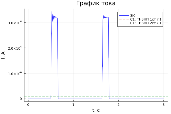


You can try to change the cycle yourself for automatic testing of the TPP kit on the C2 side. The tooltip contains a loop for testing the second set.
Hint
Restriction
When testing the second set, a limitation of the developed function is revealed.
In the short-circuit mode at point K1, the alarm operation indicators in the code do not record the protection operation. The reason is that the state of the first stage is read at a time. . At this point, the current value is lower than the setpoint.
After opening the contacts of the switch on the opposite side of the line, the current increases and the first stage is triggered before the second stage.
path = engee.gcm().name
sc_locations = ["Q1", "K2", "Q3", "K4", "K5", "K6"]
paral_line_status = ["off", "on", "off", "on", "on", "SC"]
mode_decription = ["Triggering", "Triggering", "Triggering", # To protect C2 short circuit behind the back - point K5
"Triggering", "Failure to work - KZ behind your back", "Failure to work - Short circuit on L-2"]

# The name of the tested protection is being changed
protection_first_stage = "C2: TNZNP 1st L1"
protection_second_stage = "C2: TNZNP 2st L1"

for (i, sc_loc) in enumerate(sc_locations)
    println("""---Моделирование КЗ в точке $sc_loc---
    Expected result of the protection kit: $(mode_decription[i])
    L-2 line status: $(paral_line_status[i])
    """)

    # Resetting all short circuit points
    reset_sc(sc_locations)

    # Running simulations for the sc_loc short-circuit point and line status
    run_protection_sim(0.5, protection_first_stage, protection_second_stage,
                        current_signal_name = "|3I0_2|", # we use a current meter for protection on the C2 side
                        fault_location=sc_loc,
                        paral_line_status=paral_line_status[i])
end
Conclusion
In this example, automatic testing of the TNNP kit was presented. You can use the written functions to test your security suite.
What to pay attention to when using it in your model:
-
Transition time in the main function
-
Name of the setpoint parameters in
get_trip_values() -
The name of the current on the graph in
plot_current() -
In
set_parallel_line()The names of the AUV B3 and B4 and the unique settings of the AUV parameters are used. For use on multiple lines, you can add to the function the transmission of the names of the AUV and their parameters.
You can generally refine the functions used in the example to suit your needs. For example, add a function check_trip() control of power direction and response time. Or create a function to check whether the remote protection is triggered correctly.